AI technical title is built by Patsnap AI team. It summarizes the technical point description of the patent document.
a technology of cleaning air and methods, applied in the field of cleaning air, can solve the problems of deteriorating indoor environment, affecting the health of people, and affecting the health of people, and achieve the effects of reducing the number of germs, and reducing the number of infections
Active Publication Date: 2014-06-24
HISHIDA SHINGO
View PDF6 Cites 17 Cited by
Summary
Abstract
Description
Claims
Application Information
AI Technical Summary
This helps you quickly interpret patents by identifying the three key elements:
Problems solved by technology
Method used
Benefits of technology
Benefits of technology
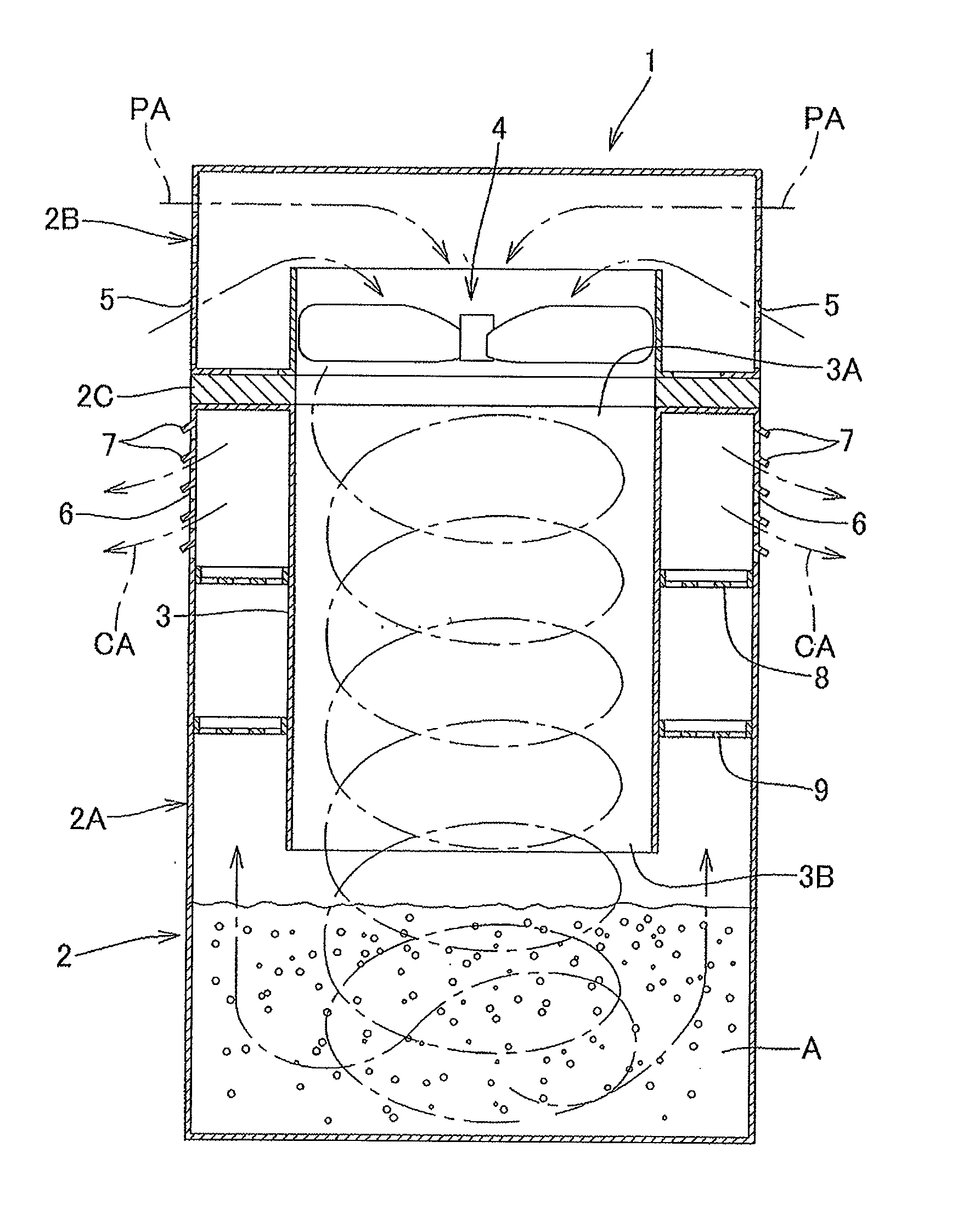
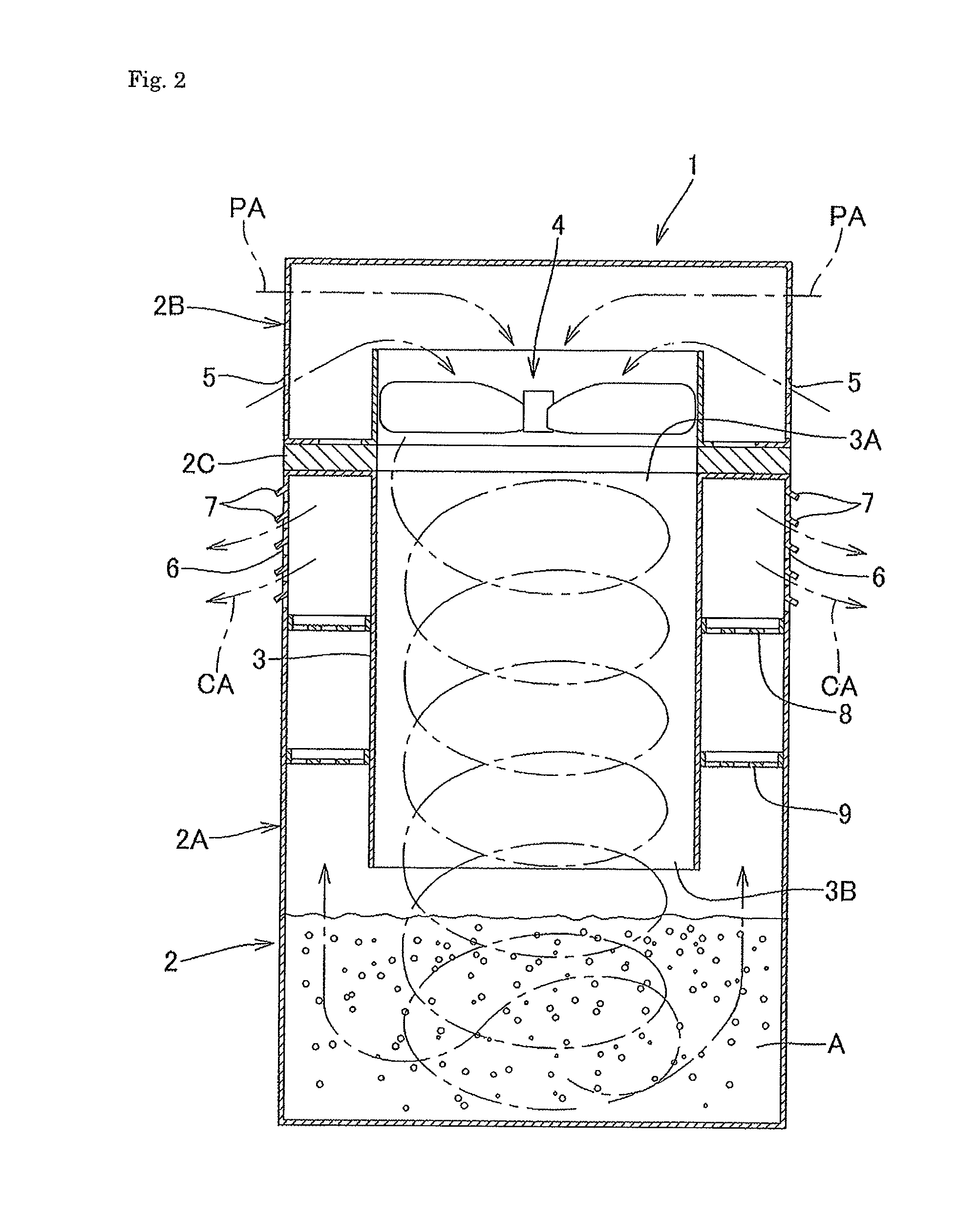
[0049]As in the foregoing, according to the air cleaning method and device in the present invention, the air taken into the container main body and pressurized by the air blower, is blown from the upper opening into the cylindrical body with the lower opening (blowing port) separated from the surface of the liquid, so as to rotate and descend in a spiral manner, and the air is strongly blown out of the lower opening as a blowing port toward the liquid surface, or a mixture formed by contacting the air spirally rotating and descending within the cylindrical body with the liquid colliding with and scattered by the reflector, is strongly blown out of the lower opening toward the liquid surface, such that the mixture collides with the liquid puddle and plunges into the bottom of the liquid containing part, whereby the air taken into the container main body is agitated and mixed with the liquid. This allows the air to contact the liquid with efficiency, thereby achieving sufficient purification of the polluted air. Accordingly, these method and device provide significant advantages of removing efficiently germs and the like from the polluted air, simplifying the structure, and suppressing increase of manufacturing costs.
Problems solved by technology
At present, indoor air in houses, hospitals, buildings, and the like, has been increasingly polluted.
These various kinds of pollutants including floating fungus and airborne infectious germs are suspended in indoor space or attached to indoor wall surfaces, ceilings, furniture, and the like, to thereby deteriorate indoor environments and exert enormous harmful effects on human bodies.
Method used
Image
Click on the blue label to locate the original text in one second.
Reading with bidirectional positioning of images and text.
Examples
Embodiment Construction
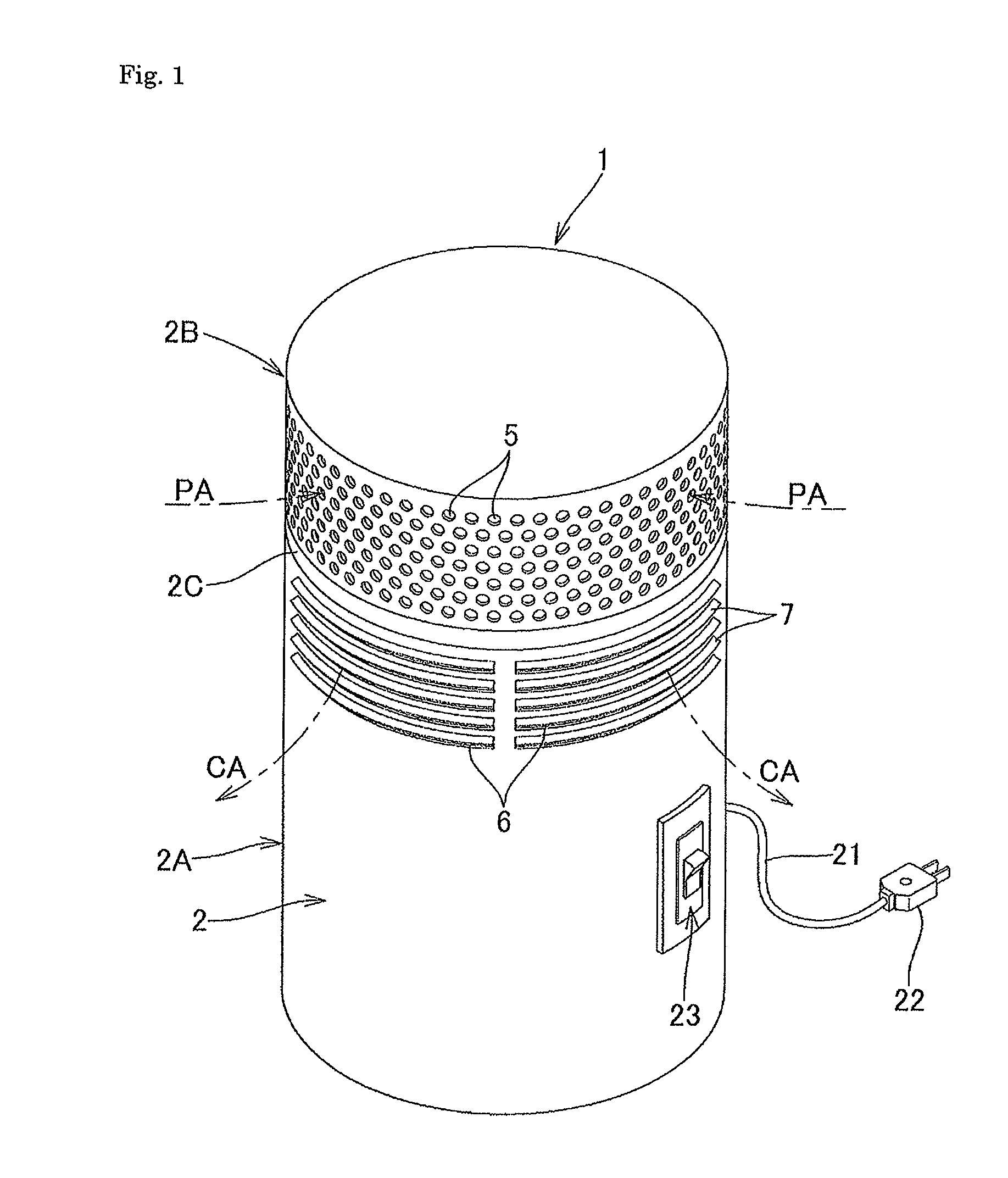
[0056]The perspective view in FIG. 1 shows an embodiment with an air cleaning device 1 for indoor use, for example, domestic use, which is brought into an operational state by inserting a power plug 22 at a leading end of a power cord 21 into a socket not shown and then turning on a switch 23.
[0057]When the air cleaning device 1 is in the operational state, polluted air PA is taken in from air inlets 5, 5, . . . formed at an upper part of a side surface of a container main body 2. The polluted air PA contacts sterilizing fluid, deodorant fluid, or water, contained in the container main body 2, and then is discharged as clean air CA with no unpleasant odor, from air outlets 6, 6, . . . .
[0058]In this arrangement, since downwardly-inclined louvers 7, 7, . . . are provided at upper edge portions of the air outlets 6, 6, . . . , the clean air CA is discharged downward from the air outlets 6, 6, . . . , thereby to suppress suction of the clean air CA from the air inlets 5, 5, . . . .
[005...
PUM
Property
Measurement
Unit
distance
aaaaa
aaaaa
diameter
aaaaa
aaaaa
time
aaaaa
aaaaa
Abstract
The present invention is to provide an air cleaning method and device that realize sufficient purification of polluted air, high-efficiency removal of germs or the like from polluted air, and has a relatively simplified structure.
Description
TECHNICAL FIELD[0001]The present invention relates to methods and devices for cleaning air to purify indoor air polluted by dust, germs, and the like.BACKGROUND ART[0002]At present, indoor air in houses, hospitals, buildings, and the like, has been increasingly polluted. Pollutants include dust, molds, ticks, pollens, and various pathogenic germs including influenza viruses, tuberculosis bacteria, methicillin-resistant Staphylococcus aureus (MRSA) as nosocomial infectious bacteria, Legionella bacteria, coronaviruses such as severe acute respiratory syndrome (SARS) viruses, noroviruses, campylobacter, O-157 as food-poisoning germs, and the like. These various kinds of pollutants including floating fungus and airborne infectious germs are suspended in indoor space or attached to indoor wall surfaces, ceilings, furniture, and the like, to thereby deteriorate indoor environments and exert enormous harmful effects on human bodies.[0003]There is suggested an air cleaning device for purify...
Claims
Application Information
Patent Timeline
Application Date:The date an application was filed.
Publication Date:The date a patent or application was officially published.
First Publication Date:The earliest publication date of a patent with the same application number.
Issue Date:Publication date of the patent grant document.
PCT Entry Date:The Entry date of PCT National Phase.
Estimated Expiry Date:The statutory expiry date of a patent right according to the Patent Law, and it is the longest term of protection that the patent right can achieve without the termination of the patent right due to other reasons(Term extension factor has been taken into account ).
Invalid Date:Actual expiry date is based on effective date or publication date of legal transaction data of invalid patent.

