External thermostat fan controller

a fan controller and thermostat technology, applied in the direction of instruments, heating types, static/dynamic balance measurement, etc., can solve the problems of not working as well in areas with high humidity, still available cooling, etc., to ensure the comfort of the homeowner, prolong the fan run time, and maintain system efficiency

Active Publication Date: 2014-07-01
LAU JAMES
View PDF7 Cites 10 Cited by
  • Summary
  • Abstract
  • Description
  • Claims
  • Application Information

AI Technical Summary

Benefits of technology

[0025]In accordance with yet another aspect, the present invention does not limit the amount of time the compressor operates and thus maintains system efficiency. The present invention relies on the thermostat to determine when the desired set point has been reached, and only then does it extend the fan run time. This ensures the homeowner's comfort and provides for the efficiency gains at the end of the cycle. The present invention also can be mounted directly at the thermostat whereas known systems require constant 24 VAC power for the use of switching relays.
[0026]In accordance with still another aspect, the present invention does nothing until the thermostat calls for heating or cooling. Once the thermostat calls for cooling or heating, the present invention can extend the fan run time for either a fixed duration or an adaptable duration based on the time the compressor was active.

Problems solved by technology

This wastes two kinds of cooling still available.
It would not work as well in areas with high humidity.

Method used


Image

  • External thermostat fan controller
  • External thermostat fan controller
  • External thermostat fan controller

Examples


Embodiment Construction

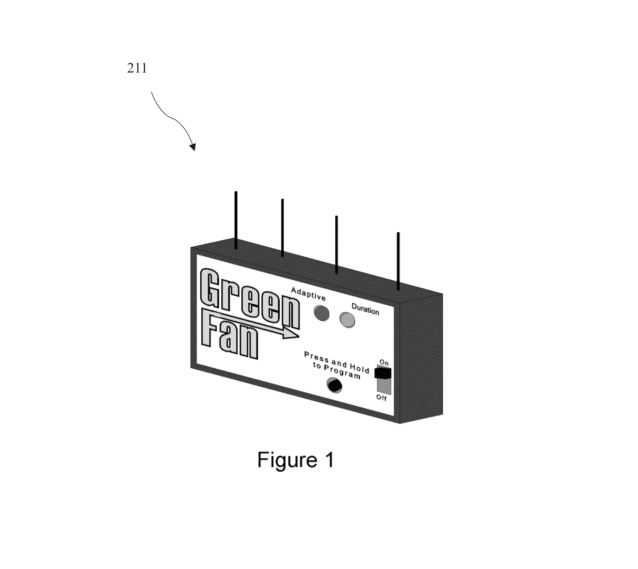
[0060]FIG. 1 is a pictorial illustration of a fan controller 211 according to the present invention. The fan controller 211 can connect directly to an existing thermostat through the use of only three wires. It can be mounted on the wall near the thermostat or located anywhere else in the house, as long as it can be connected to the thermostat wires.

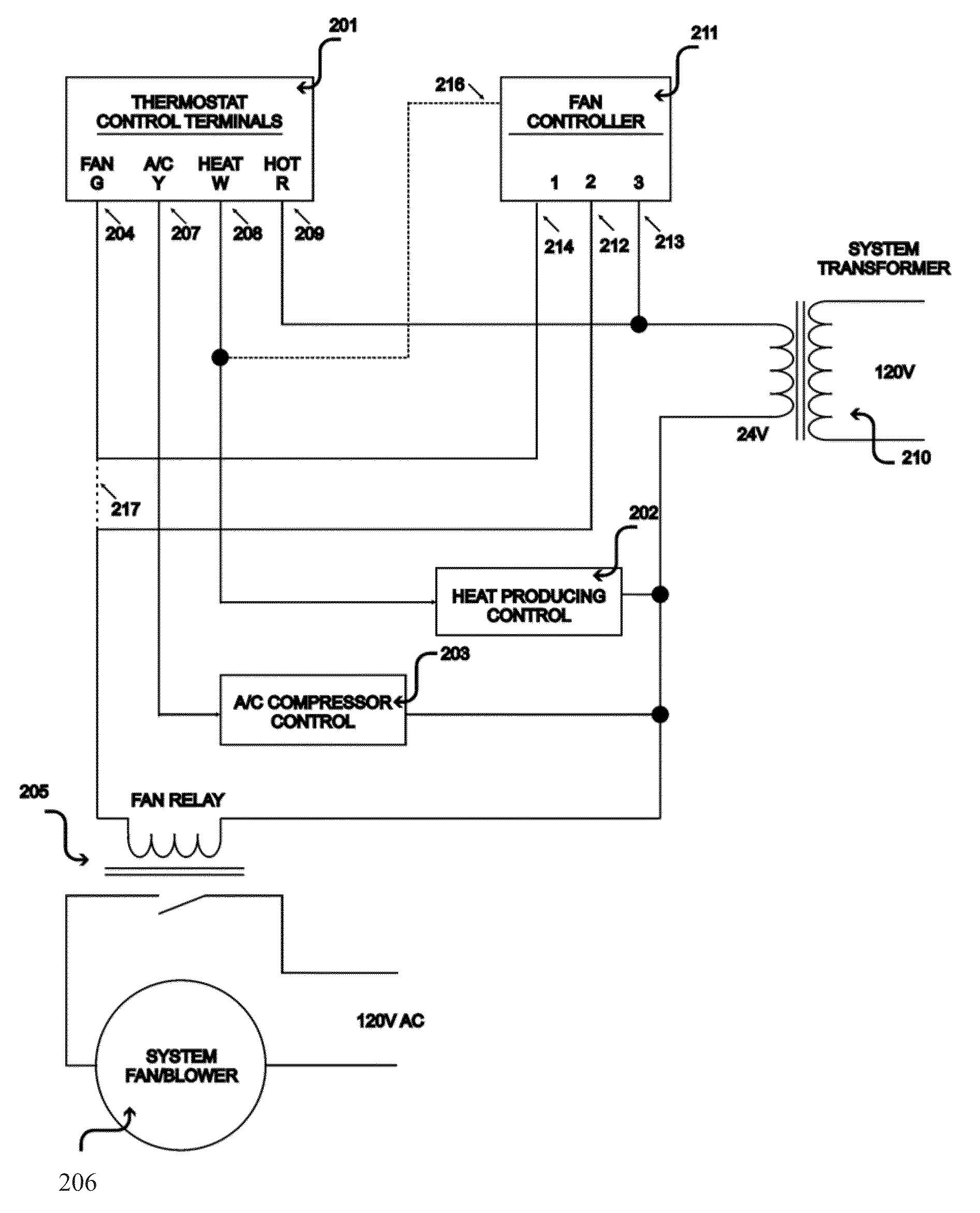
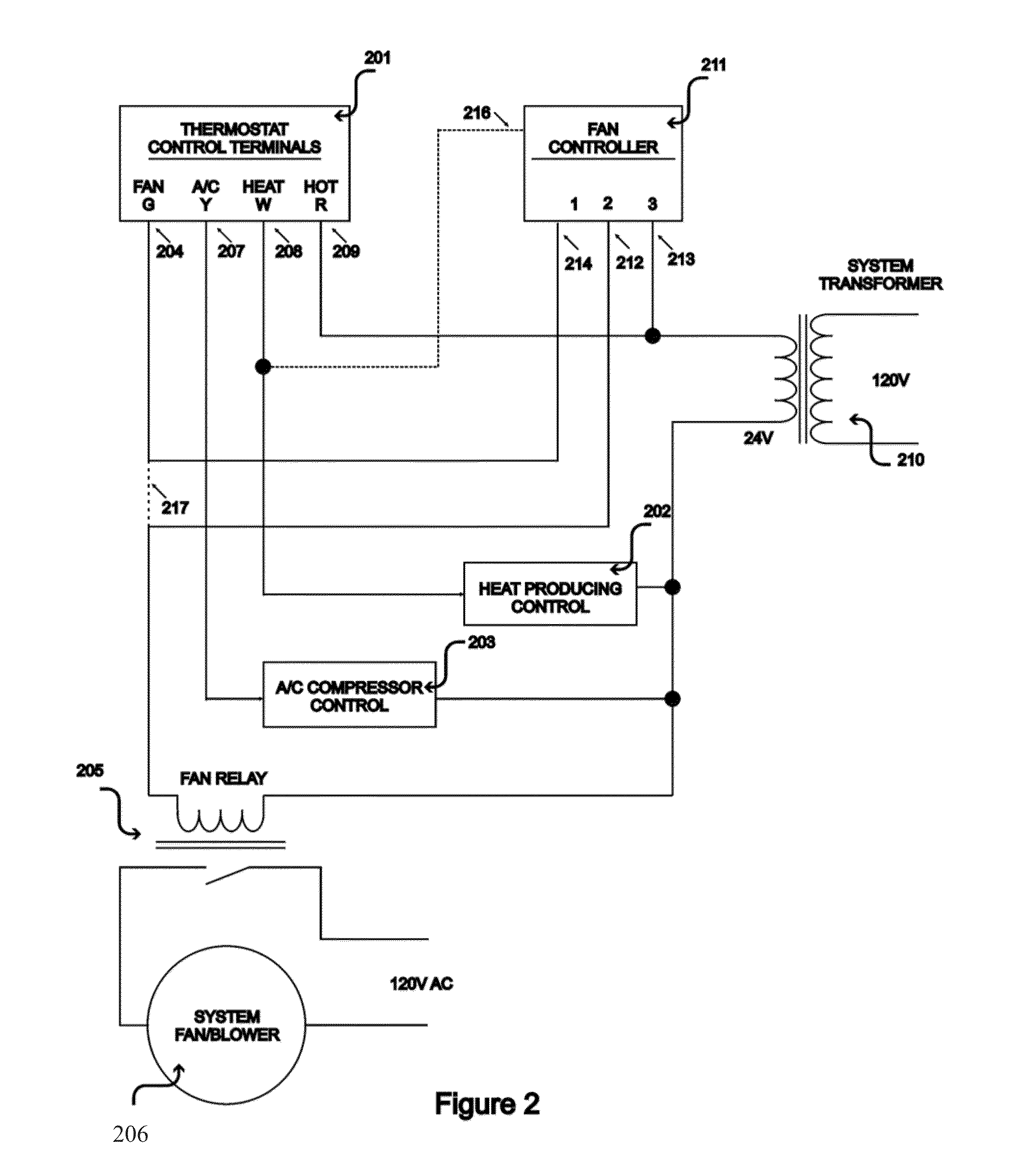
[0061]FIG. 2 illustrates, in block diagram form, the configuration of the present invention in relation to an existing household thermostat 201. The thermostat 201 is typically connected as shown when the home has a furnace / heat producing control circuitry 202 and air conditioning compressor control 203. Prior to the installation of the present invention, the fan contact terminal 204 connects the thermostat 201 to the fan / blower relay 205. With the addition of the fan controller 211, this connection is interrupted as shown by dashed line 217 and the terminal 204 is connected to terminal 214 of the fan controller 211 and terminal 212 of t...


PUM


Abstract

A programmable controller circuit that can be connected directly to the fan switch of any thermostat with a forced air heating and/or cooling system that includes a blower fan for circulating air throughout the home. The controller can be installed with minimal modifications to the existing wiring. The present invention increases the efficiency of the cooling system by evaporating condensate and extracting residual coolness from the thermal mass of the evaporator coils. The present invention can be programmed with a single button. A method of adapting additional fan run time based on compressor run time.

Description

CROSS REFERENCE TO RELATED APPLICATIONS[0001]This application claims the benefit of provisional patent application Ser. No. 61 / 324,229 filed 2010 Apr. 14 by the present inventor.FEDERALLY SPONSORED RESEARCH[0002]Not applicable.SEQUENCE LISTING OR PROGRAM[0003]Not applicable.BACKGROUND OF THE INVENTION[0004]1. Field of the Invention[0005]This invention is a device for extending the run time of an air conditioning fan after the compressor stops and thereby increasing the cooling / heating output and in the case of air conditioning, increasing the Sensible Energy Efficiency Ratio (SEER).[0006]2. Description of the Related Art[0007]U.S. Pat. No. 5,142,880 (Bellis, 1992) discloses a solid state control circuit for use in connection with existing low-voltage thermostat terminals of a central, forced-air, air conditioning system having a compressor and an indoor blower and gas-fired or electrical heating elements. The '880 patent relates generally to systems for increasing the efficiency of ...

Claims


Application Information

Patent Timeline
Patent Type & Authority Patents(United States)
IPC IPC(8): G05D23/19G05D23/00
CPCG05D23/19G05D23/00F24F1/22F24F11/70F24F11/89Y02B30/70
Inventor WALSH, JOHN
Owner LAU JAMES
Why Eureka
Try Eureka