Non pressure compensated drip irrigation emitter with multiflow facility

a drip irrigation and multi-flow technology, applied in watering devices, horticulture, agriculture, etc., to achieve the effect of eliminating all deficiencies

Inactive Publication Date: 2014-07-01
PATEL PARIXIT AMRUTBHAI
View PDF7 Cites 28 Cited by
  • Summary
  • Abstract
  • Description
  • Claims
  • Application Information

AI Technical Summary

Benefits of technology

[0029]The main object of the present invention is to provide a drip irrigation emitter which eliminates all deficiencies associated with the prior art emitters.
[0031]Yet another object of the invention is to provide a non pressure compensated drip irrigation emitter which regulates the release of water more accurately and gives continuous flow of discharge even in case of partial clogging into the labyrinth.
[0033]Yet another object of the invention is to provide a non pressure compensated drip irrigation emitter which is placed inline into the emitting pipe so as to prevent it from damage by the applied load which in any case may by tractor or other instruments at work fields.
[0034]Yet another object of the invention is to provide a non pressure compensated drip irrigation emitter which is easy to design and very inexpensive.

Problems solved by technology

Irrigation is pouring water to the soil using proper methods and in proper times as required by the plant growth as a result of insufficient rain.
With the application of water to the land surface does not always accomplish the intended purpose.
Much of this water is lost due to evaporation, run-off, percolation passed the root zone and so on.
Surface irrigation systems are typically less efficient in applying water than pressure irrigation methods.
Many are situated on lower lands with heavier soils and, therefore, tend to be more affected by water logging and soil salinity if adequate drainage is not provided.
Surface systems tend to be labour-intensive.
Another disadvantage of surface irrigation methods is the difficulty in applying light, frequent irrigations early and late in the growing season of several crops.
But there are many disadvantages associated with this kind of irrigation.
Some of them are more usage of water compared to drip irrigation high cost of power, wind interferes with the distribution pattern and nozzle clogging.
However, a hole alone does not work well.
Unless the hole is extremely small, the water tends to forcefully shoot out of it like a tiny fire nozzle and way too much water comes out.
More importantly, there is little uniformity of flow when using a simple hole.
Pressure compensated emitters are designed to discharge water at a very uniform rate under a wide range of water pressure which is more expensive than the Non pressure compensated (Non PC) emitters and also not suitable for all types of drip irrigation systems.
Emitter clogging, which is formed in a short time due to irrigation systems' running under an inadequate pressure or owing to water quality, not only negatively influences uniformity of water distribution but also causes inadequate irrigation.
The small openings of the emitter can be easily clogged by soil particles, organic matter, bacterial slime, algae or chemical precipitates effects water and fertilizer uniformity, increase maintenance costs, and cause crop damage.
1. Available Single emitter for different discharge through multi outlet has following disadvantages:These types of emitters have single discharge from single outlet and double discharge from two outlets.These types of emitter have multi oriented inserting option.These types of emitters have separate flow path for single discharge which can allow clogging of one outlet.These emitters require two drilling within one emitter for higher or multiple discharge which increases complexicity of drilling vis-à-vis more initial cost. These types of emitters have high installation and maintenance cost.
2. Available non-clogging, non-pressure compensated drip emitter utilizes one or more filters to prevent clogging in the labyrinth. The water that enters the emitter also contains suspended soil particles which are not accurately filtered by the provided filters. This causes clogging into the labyrinth.
3. Available drip irrigation system uses Pressure compensated type emitter has higher initial investment costs and marginally higher operating costs compared to systems using non-pressure compensated emitters. To overcome the problem of clogging greater water filtration is generally required for these emitters.
4. The available emitters has to inserted unidirectional, which reduces the efficacy of the production of emitting pipes.
From above it is clear that the forgoing prior art emitters have various problems, mostly dealing with water pressure and water clogging in the labyrinth.

Method used


Image

  • Non pressure compensated drip irrigation emitter with multiflow facility
  • Non pressure compensated drip irrigation emitter with multiflow facility
  • Non pressure compensated drip irrigation emitter with multiflow facility

Examples


Embodiment Construction

[0056]The features, nature, and advantages of the disclosed subject matter will become more apparent from the detailed description set forth below when taken in conjunction with the drawings in which like reference numerals identify correspondingly throughout.

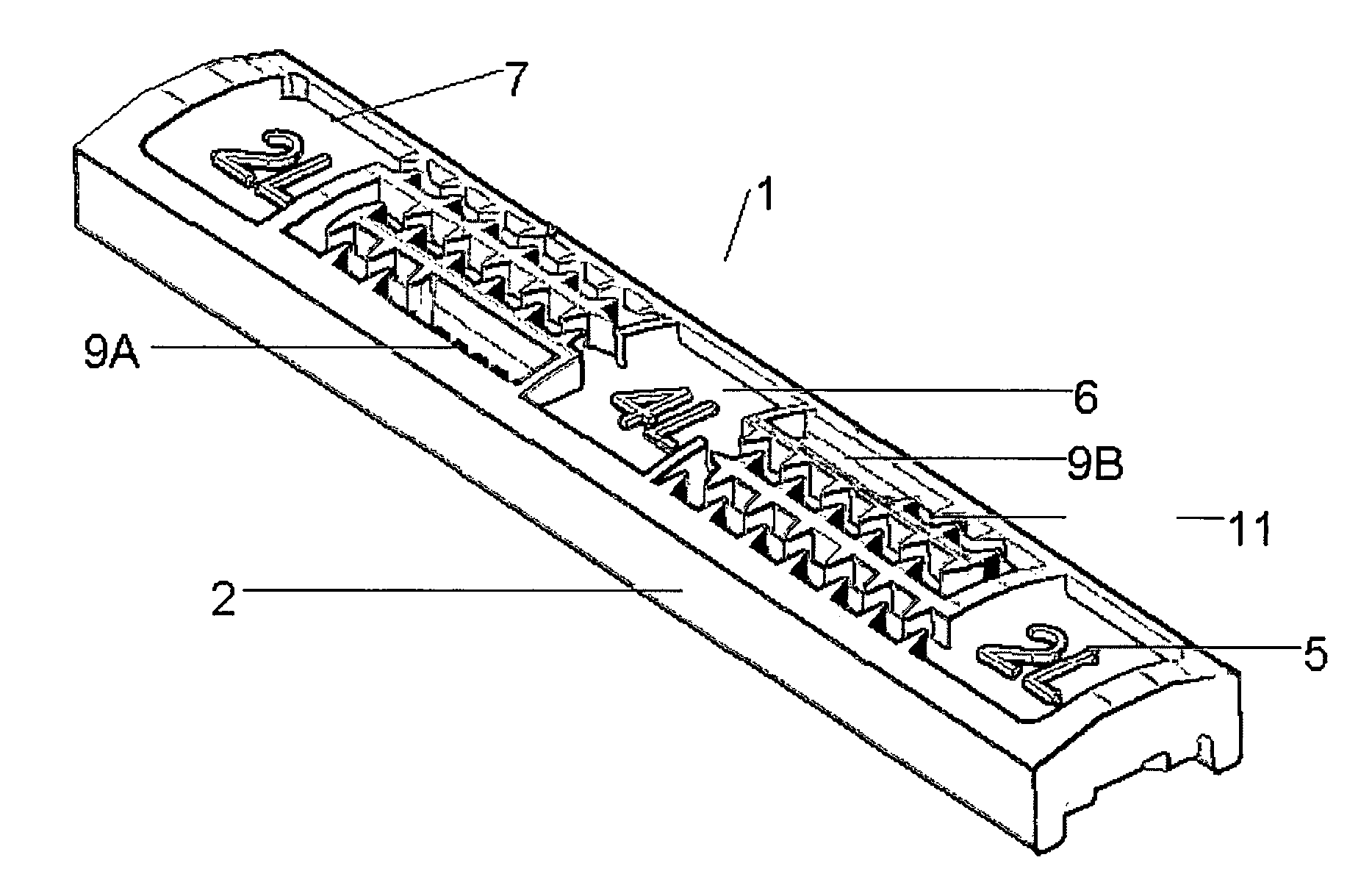
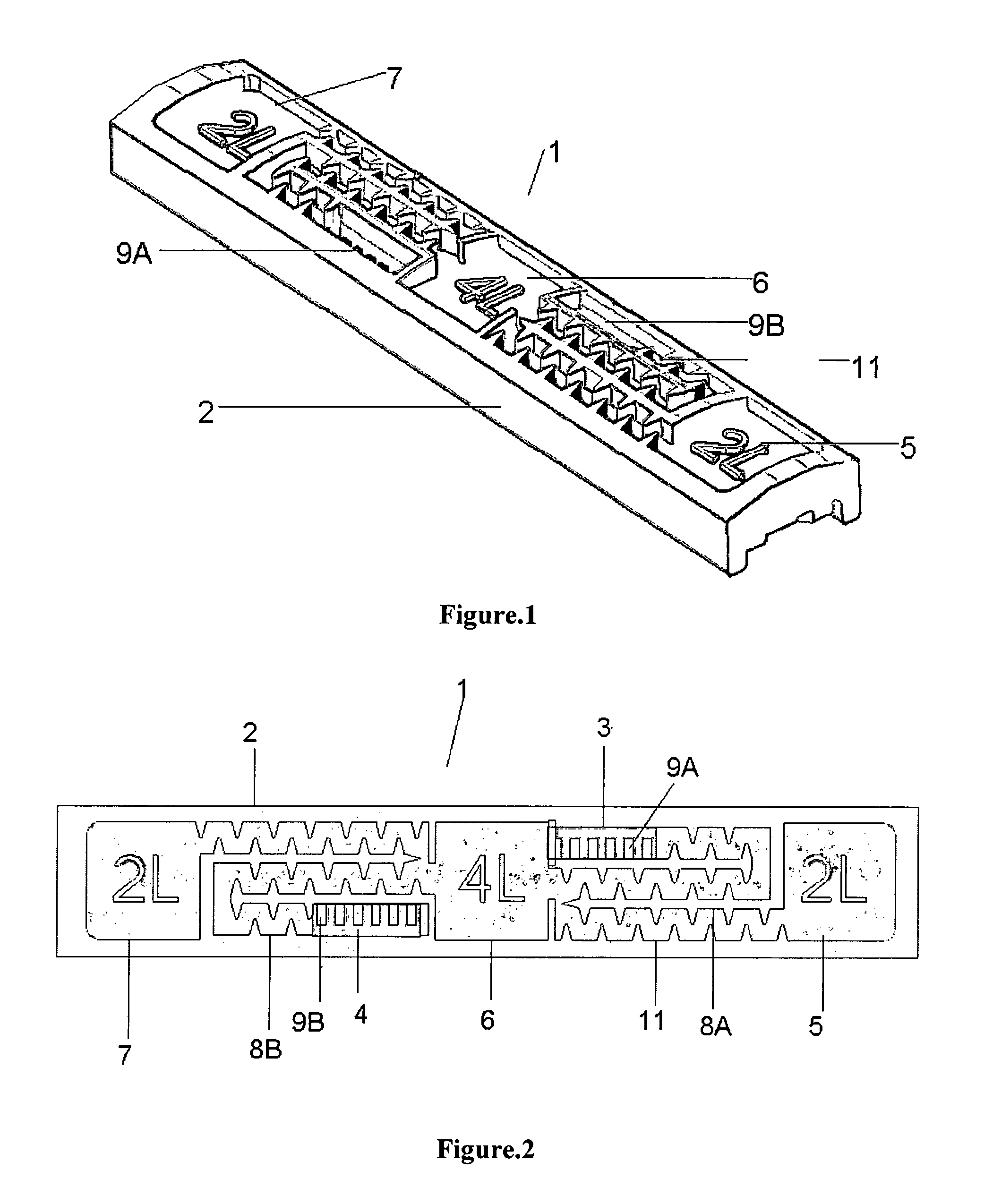
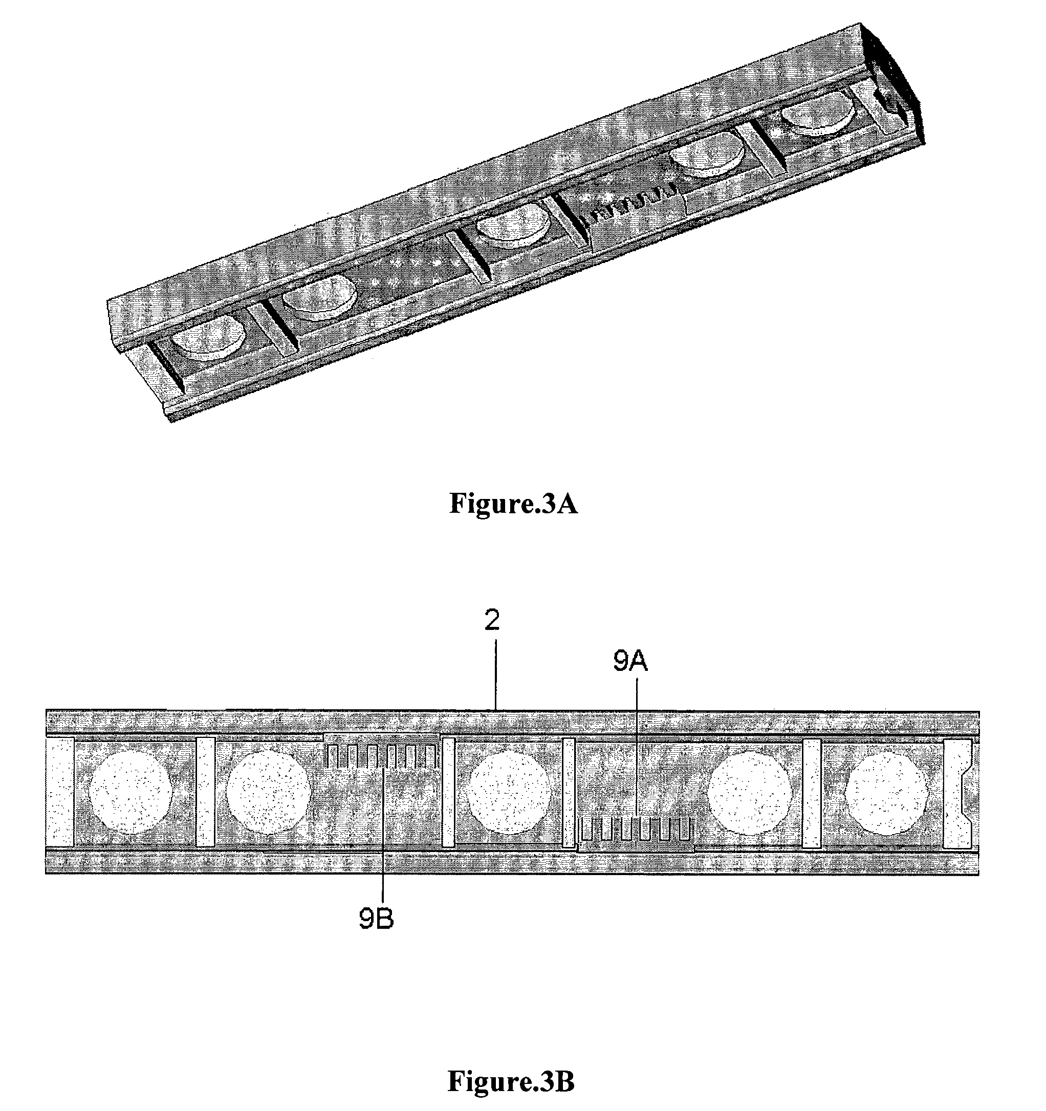
[0057]Referring to FIGS. 1 to 5, the non pressure compensated drip emitter (1) with multiflow facility comprises single outlet (10) for different discharge flow rate with two entry points (3, 4). The emitter mainly includes minimum two entry points (3, 4) for water with single outlet (10), filters (9A, 9B) at each entry points and a common labyrinth for flow of water (8A, 8B). The filters (9A, 9B) filter the coming water to emitter for minimizing clogging.

[0058]The emitter (1) includes three pools named 1st pool (5), middle pool (6) and 3rd pool (7) wherein the 1st pool and 3rd pool discharge same flow of water in droplets when either of them is punched. The middle pool (6) discharges different flow of water in droplets. The mi...


PUM


Abstract

Described is a non pressure compensated drip emitter with multiflow facility, the drip emitter being placed inside a pipe of a drip irrigation system, the drip emitter comprising: a housing; a filter system being fitted at each inlet to ensure pure supply of water inside the emitter; three pools of water from only one of which water get discharged out of emitter and from emitter to the land to be irrigated, the third pool in the middle; a labyrinth in fluid communication with each pool and the filter system, the labyrinth comprises zigzag water paths; wherein the labyrinth connects middle pool with remaining two pools through the zigzag water path in such a way that even in case of partial clogging of the zigzag water path, the remaining partial zigzag water path remain active and ensure the discharge of water at a selected flow rate from the emitter.

Description

CROSS REFERENCE TO RELATED APPLICATIONS[0001]This is the U.S. National Stage of International Application No. PCT / IN2011 / 000072 filed Feb. 1, 2011, which was published in English under PCT Article 21(2), which in turn claims the benefit of Indian Application No. 274 / MUM / 2010, filed Feb. 3, 2010. Both applications are hereby incorporated by reference herein in their entirety.FIELD OF THE INVENTION[0002]The present invention generally relates to drip irrigation equipment. More particularly it relates to a drip irrigation emitter and most specifically it relates to a non pressure compensated drip irrigation emitter with multiflow facility.BACKGROUND OF THE INVENTION[0003]Irrigation is pouring water to the soil using proper methods and in proper times as required by the plant growth as a result of insufficient rain. The success of irrigation depends on the selection of the most proper irrigation method as per the conditions and planning, projecting, establishing and operating the irriga...

Claims


Application Information

Patent Timeline
Patent Type & Authority Patents(United States)
IPC IPC(8): B05B15/00
CPCA01G25/023Y02A40/22
Inventor PATEL, PARIXIT, AMRUTBHAI
Owner PATEL PARIXIT AMRUTBHAI
Why Eureka
Try Eureka