Eureka AIR delivers breakthrough ideas for toughest innovation challenges, trusted by R&D personnel around the world.

Seal arrangement, especially for high pressure applications, preferably for use in CO.sub.2 compressors

a high-pressure application and sealing arrangement technology, applied in the direction of engine seals, engine components, mechanical apparatus, etc., can solve the problems of excessive leakage and higher wear of mechanical shaft seal parts, and achieve the effect of increasing the sealing tightness of the arrangement and reducing the wear of sliding partners

Inactive Publication Date: 2014-07-01
KACO
View PDF19 Cites 3 Cited by
  • Summary
  • Abstract
  • Description
  • Claims
  • Application Information

AI Technical Summary

Benefits of technology

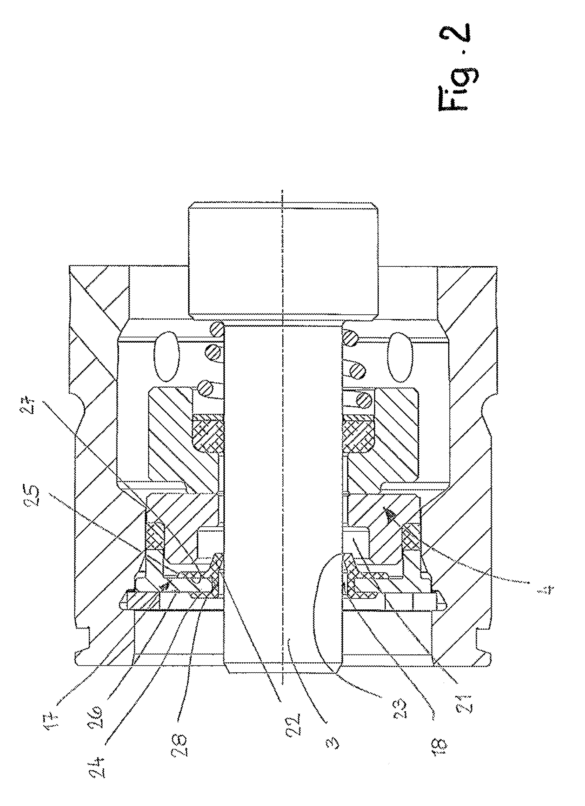
[0005]In the seal arrangement according to the invention by means of the additional sealing lip the seal-tightness of the arrangement is increased. In particular during the initial running-in of the sliding surfaces of annular counter member and slide ring this sealing lip is particularly advantageous because it reliably catches medium that has escaped through the sealing gap. As a result of the sealing lip the pressing force with which the two sliding partners of the mechanical shaft seal are forced against one another can be relatively small so that wear of the sliding partners is also correspondingly reduced.

Problems solved by technology

In particular, during the initial running-in of the sealing surfaces of annular counter member and slide ring there is the problem that as a result of not yet properly seated (run-in) sealing surfaces excess leakage is observed.
The increased pressing force causes higher wear of the mechanical shaft seal parts.

Method used


Image

  • Seal arrangement, especially for high pressure applications, preferably for use in CO.sub.2 compressors
  • Seal arrangement, especially for high pressure applications, preferably for use in CO.sub.2 compressors
  • Seal arrangement, especially for high pressure applications, preferably for use in CO.sub.2 compressors

Examples


Embodiment Construction

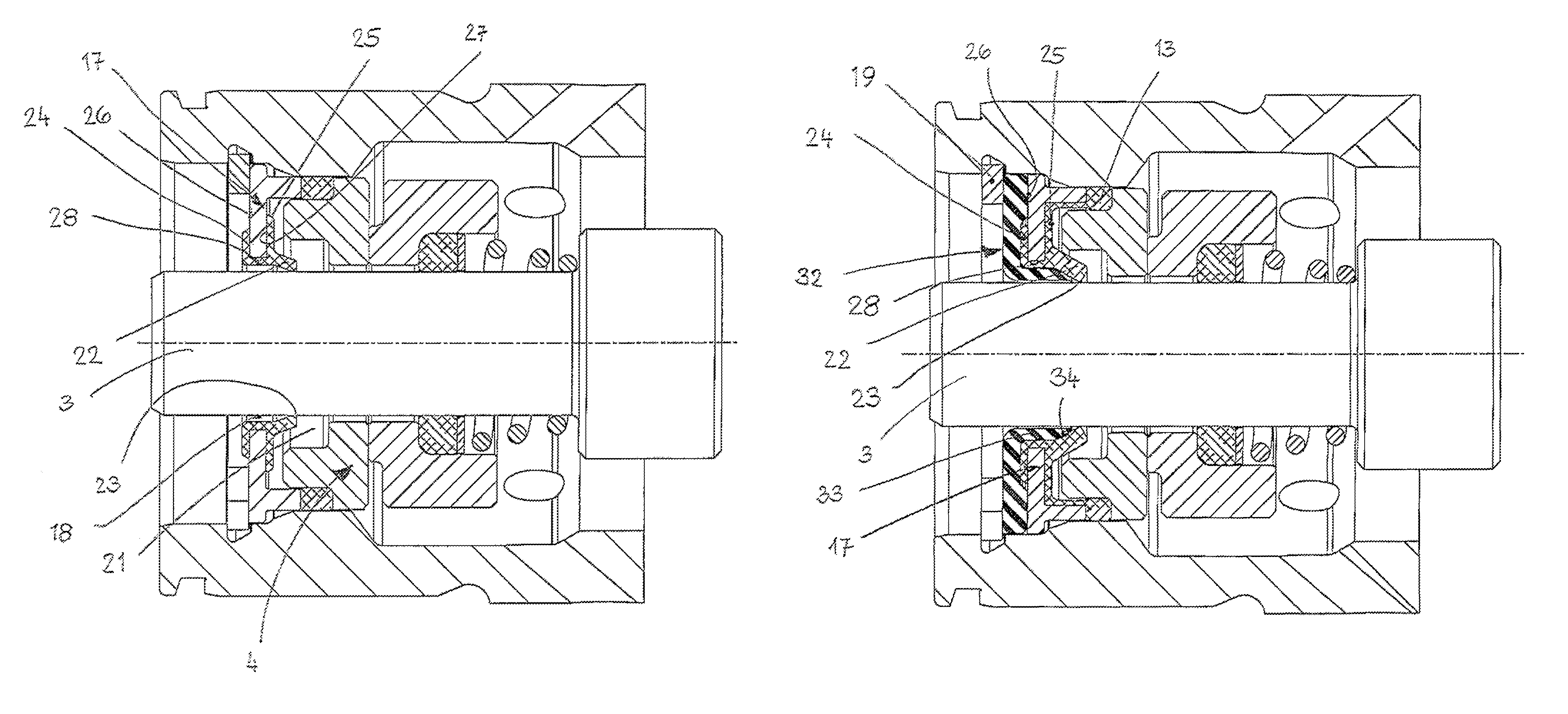
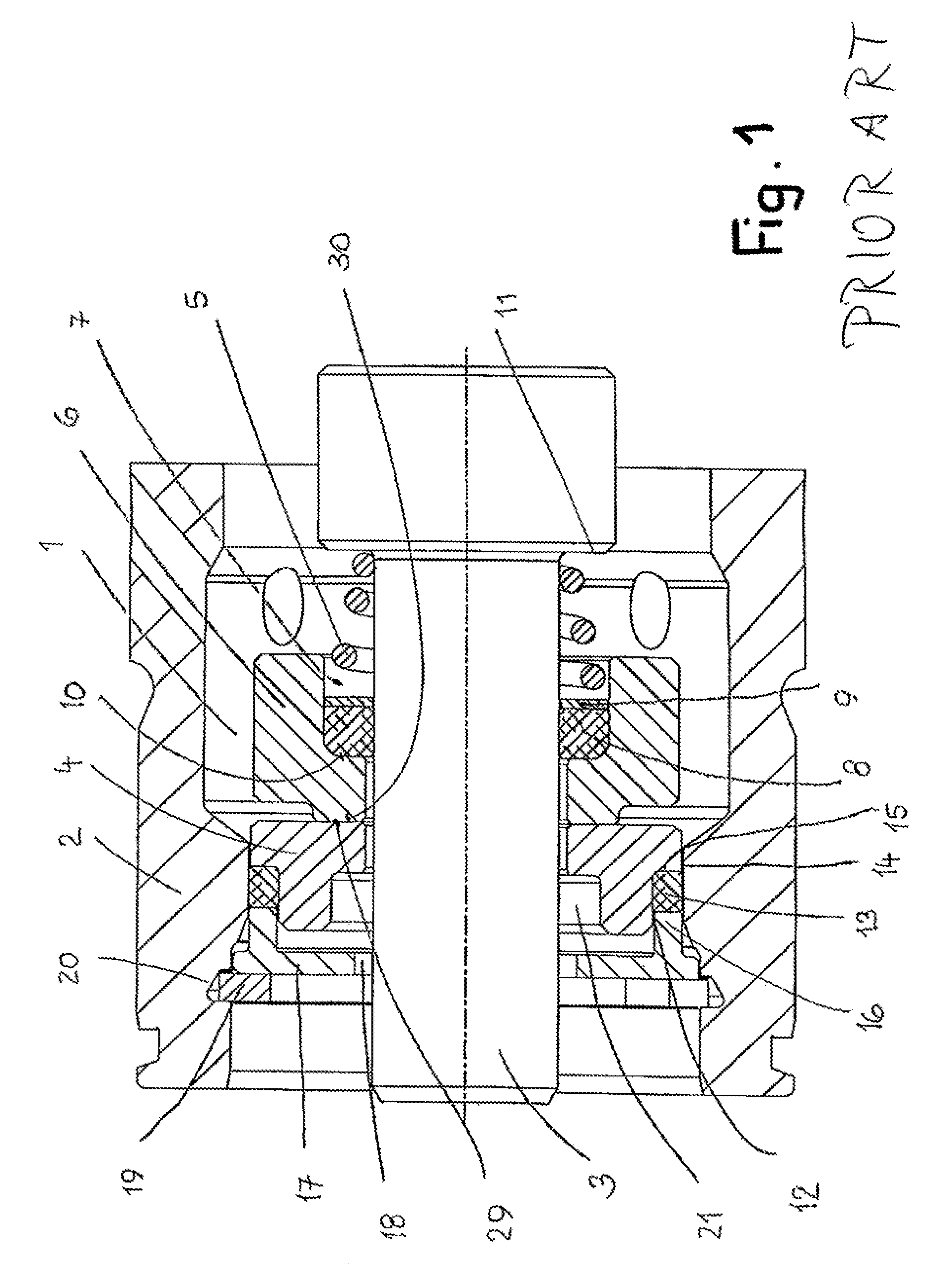
[0013]FIG. 1 shows a seal arrangement in the form of a mechanical seal according to the prior art. The mechanical seal is designed for high-pressure applications, in particular for CO2 compressors. The seal arrangement is located in a mounting space 1 of a housing 2. A machine part 3 to be sealed, such as a shaft, projects through the mounting space 1. The seal arrangement has an annular counter member 4 against which a slide ring 6 rests seal-tightly under the force of at least one pressure spring 5. The slide ring 6 surrounds the machine part 3 at a minimal spacing and has its inner side an annular recess 7 in which a driving collar 8 is positioned with which the slide ring 6 is fixedly connected to the machine part 3. The driving collar 8 is comprised e.g. of rubber and is axially secured in the mounted position by a securing ring 9 in the recess 7. The driving collar 8 rests against the radial end face 10 that is proximal to the annular counter member 4. On the securing ring 9 a...


PUM


Abstract

A seal arrangement has a mechanical shaft seal with an annular counter member and a slide ring each having sliding surfaces that rest against one another and define sealing gap. The sealing gap has at least one sealing lip correlated therewith. The sealing lip is arranged downstream or upstream of the sealing gap.

Description

BACKGROUND OF THE INVENTION[0001]The invention relates to a seal arrangement, in particular for high-pressure applications, preferably for use in CO2 compressors, comprising a mechanical seal comprised of a slide ring and an annular counter member, wherein the slide ring and annular counter member rest with their sliding surfaces against one another and define a sealing gap.[0002]In known seal arrangements that are used in particular in high-pressure applications, a mechanical shaft seal is used. The sealing gap between the annular counter member and the slide ring seals the medium and prevents its escape. In particular, during the initial running-in of the sealing surfaces of annular counter member and slide ring there is the problem that as a result of not yet properly seated (run-in) sealing surfaces excess leakage is observed. For this reason, the slide ring is pressed with an appropriately great force against the annular counter member in order to improve the seal-tightness of ...

Claims


Application Information

Patent Timeline
Patent Type & Authority Patents(United States)
IPC IPC(8): F16J15/32
CPCF16J15/002F16J15/3252F16J15/348F16J15/38
Inventor SCHWERDTFEGER, MARKUS
Owner KACO
Why Eureka
Eureka Blog
Learn More