Meter illumination device

a technology of illumination device and meter, which is applied in the direction of control device, measurement apparatus components, instruments, etc., can solve the problems of increasing the weight of the entire device, complicated illuminating structure, and increasing the cost of components, and achieves bright illumination and sufficient illumination brightness of the indicating needl

Inactive Publication Date: 2014-07-01
NIPPON SEIKI CO LTD
View PDF7 Cites 5 Cited by
  • Summary
  • Abstract
  • Description
  • Claims
  • Application Information

AI Technical Summary

Benefits of technology

[0010]In view of such problems described above, it is an object of the present invention to provide a meter illumination device which is capable of displaying an indicating needle and markings of a display panel by illumination with sufficient brightness even with a relatively small number of luminous sources.

Problems solved by technology

However, since the light guide is required, there is a problem in that the cost of the components and the weight of the entire device are increased, and the illuminating structure becomes complicated.

Method used


Image

  • Meter illumination device
  • Meter illumination device
  • Meter illumination device

Examples


Embodiment Construction

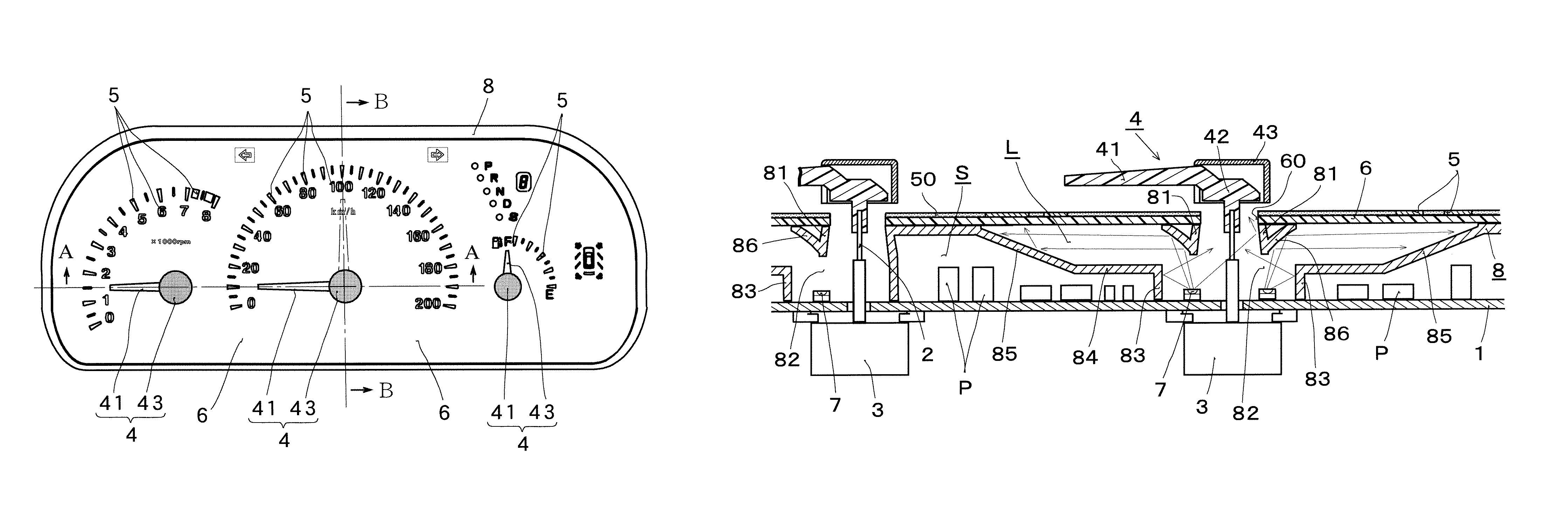
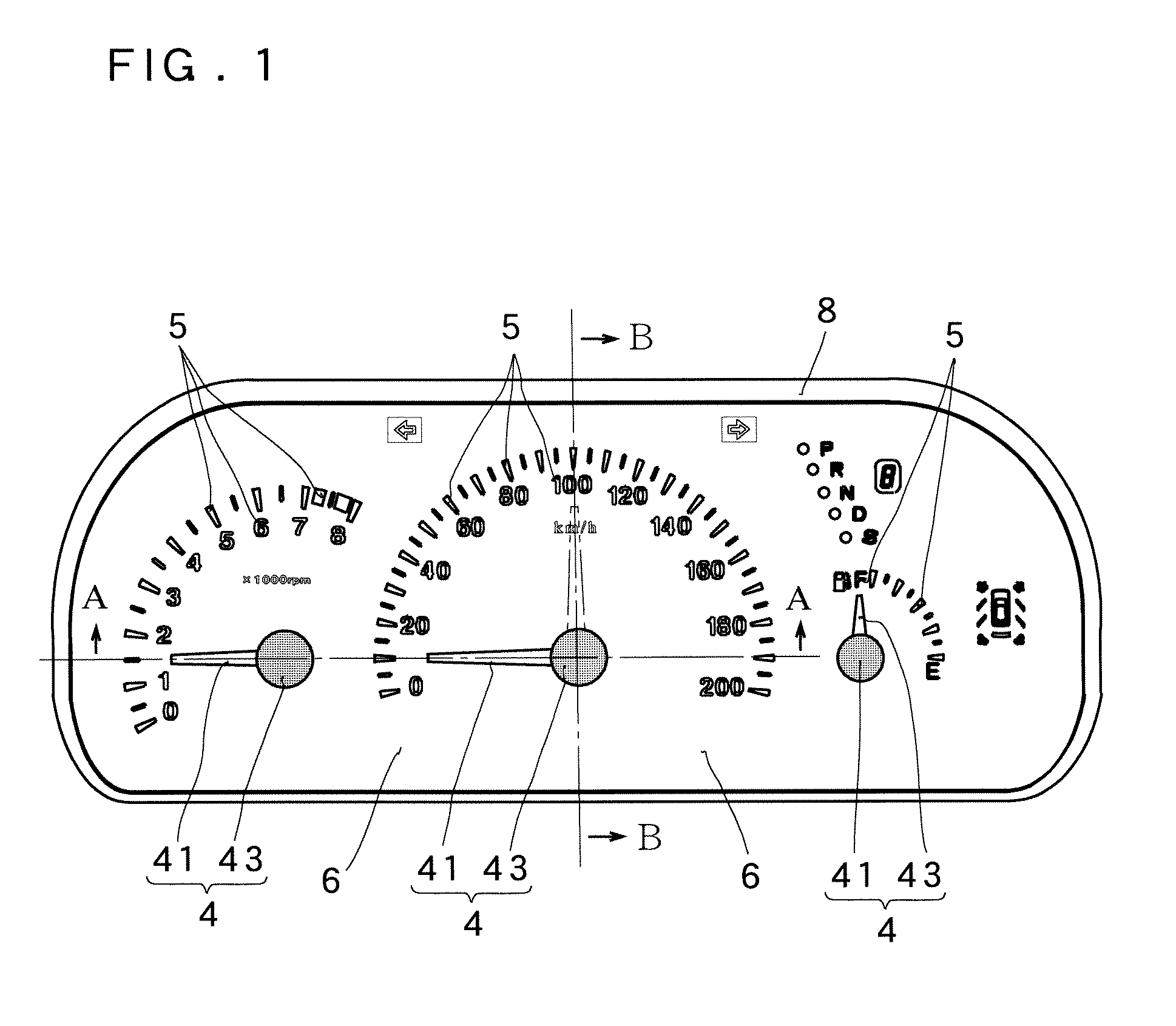
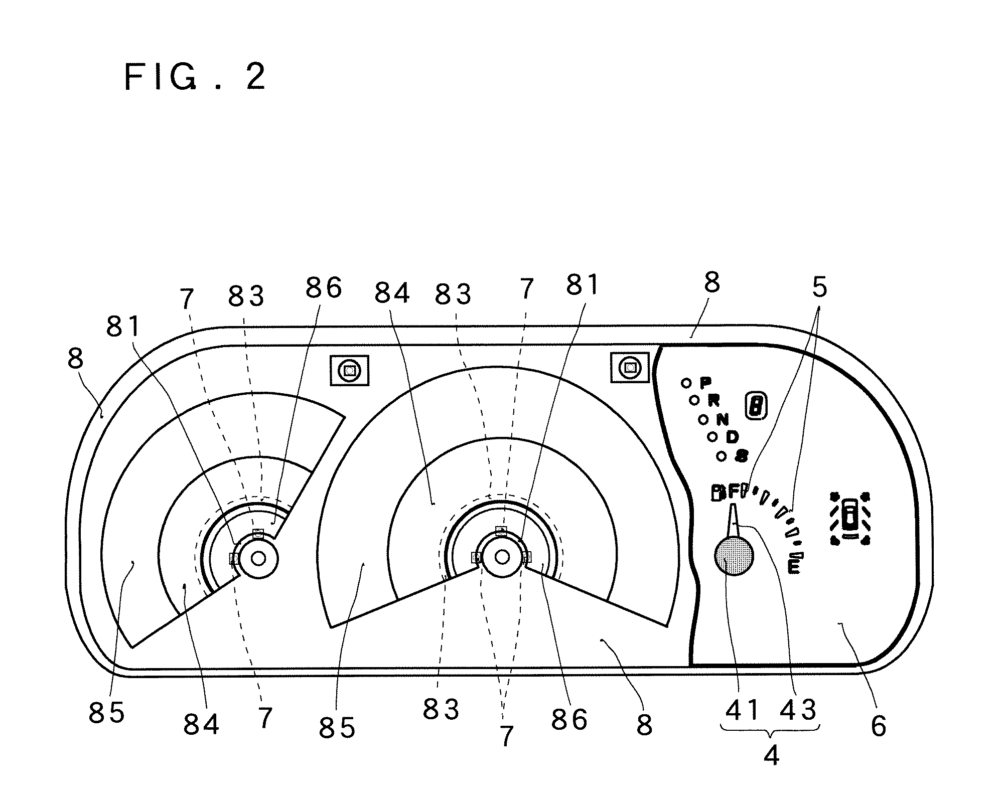
[0027]FIG. 1 to FIG. 5 show an embodiment of the present invention, and a case in which the embodiment of the present invention is applied to a meter illumination device in an indicating meter mounted, for example, on an automotive vehicle, with reference to these drawings.

[0028]In the drawings, the meter illumination device of an indicating needle type indicating meter according to the embodiment includes a circuit board 1, a meter body 3 conductively mounted on the circuit board 1 and having a drive shaft 2 extending toward the front, a light-emitting type indicating needle 4 mounted on the distal end side of the drive shaft 2, a display panel 6 arranged between the indicating needle 4 and the circuit board 1 and having markings 5 corresponding at least to indication of the indicating needle 4, luminous sources 7 mounted on the side of the front surface of the circuit board 1 and configured to light the indicating needle 4 and the markings 5 therethrough, a meter housing 8 arrange...


PUM


Abstract

Disclosed is a meter illumination device which makes it possible to sufficiently illuminate the indicating sections of the indicating needle and the display panel. A meter housing (8) is equipped with a light guide tube (81) that guides light rays from a light source (7) to the base (42) end of an indicating needle (4); a light guide opening (82) that is provided between the bottom end of the light guide tube (81) and a circuit board (1); an upright reflective circumferential wall section (83) that surrounds the periphery of the light guide opening (82) and is provided at a prescribed distance from the light source (7); a first reflective wall section (85) that is provided in order to perform transmission illumination of the indicating section (5) regions of a display panel (6), and that is contiguous with the upper end of the upright reflective circumferential wall section (83); and a second reflective wall section (86) having a substantially inverted conical shape provided at a point on the outer periphery of the light guide tube (81) for reflectively directing light onto the first reflective wall section (85).

Description

RELATED APPLICATIONS[0001]This application is the U.S. National Phase under 35 U.S.C. §371 of International Application No. PCT / JP2010 / 058257, filed on May 17, 2010, which in turn claims the benefit of Japanese Application No. 2009-129926, filed on May 29, 2009, the disclosures of which Applications are incorporated by reference herein.TECHNICAL FIELD[0002]The present invention relates to a meter illumination device configured to display an indicating needle and a display panel of an indicating meter by illumination.BACKGROUND ART[0003]As a meter illumination device of this type, there is a known type having a configuration in which a meter body having a drive shaft provided so as to project therefrom is mounted on a circuit board, an indicating needle which is lit upon receipt of illuminating light from the side of a center of rotation is mounted at a distal end of the drive shaft, a display panel (dial panel) having translucent markings such as calibration markings or characters a...

Claims


Application Information

Patent Timeline
Patent Type & Authority Patents(United States)
IPC IPC(8): G01D11/28
CPCG01D11/28B60K37/02B60K2350/203B60K2350/2039B60K2350/402B60K2350/408B60K2370/33B60K2370/34B60K2370/695B60K2370/698B60K2370/336
Inventor TOMONO, KOICHIISHIZUKI, SATOSHI
Owner NIPPON SEIKI CO LTD
Why Eureka
Try Eureka