Apparatus for the supply of products

a technology for products and accessories, applied in the direction of conveyors, mechanical conveyors, conveyor parts, etc., can solve the problems of installation, maintenance and repair, and the need to provide the plurality of pivot bearings, so as to facilitate the independent pivoting and simplify maintenance and cleaning.

Inactive Publication Date: 2014-07-08
WEBER MASCHENBAU
View PDF13 Cites 4 Cited by
  • Summary
  • Abstract
  • Description
  • Claims
  • Application Information

AI Technical Summary

Benefits of technology

[0007]According to an embodiment of the invention, the support structure is movably supported by a jointed arm arrangement at a support element spaced apart from the drive shaft such that by moving the jointed arm arrangement, the support structure can be pivoted about the drive shaft's axis of rotation. The support structure is therefore pivoted about a virtual axis of rotation which coincides with the drive shaft's axis of rotation. Due to the support structure being supported at an element spaced apart from the drive shaft, a real pivot connection, i.e. a structural pivot connection, between the support structure and the drive shaft can be omitted, whereby the respective bearings and seals can be saved. Since the support element does not need to rotate at the rotational speed of the drive shaft, simple, inexpensive and reliable sliding bearings can be used instead of roller element bearings for supporting the jointed arm arrangement at the support element. This increases the life cycle of the conveyor apparatus and reduces failure-related downtimes. Avoiding a real pivot connection between the support structure and the drive shaft is also advantageous from a hygienic perspective. The support element may be rigid and in particular fixed to the housing. In so far as several conveyor devices are provided, a common support element may be provided for all conveyor devices in order to save effort and costs.
[0014]Each jointed arm assembly may comprise a four-joint link, where the support element forms a fixed point of the four-joint link. In particular, the or each jointed arm arrangement can comprise parallel kinematics with two parallel levers which may be of equal length being pivotably connected to the support structure at linkage points spaced from each other. In this respect, one of the parallel levers may be movably supported at the support element via a displacement lever. The displacement lever allows an end of the support structure to be displaced from the drive shaft while forming a free space interrupting the supporting connection between the support structure and the drive shaft.

Problems solved by technology

In particular, for a plurality of adjacently arranged conveyor devices, the problem arises in this respect, however, that a plurality of pivot bearings must be provided, which must have a correspondingly low-friction design due to the generally relatively high rotational speed of the drive shaft.
This, however, gives rise to problems in the production of the drive shaft since the stringent tolerance requirements for the bearing seats have to be satisfied along the entire length of the drive shaft.
There are also problems in the installation, maintenance and repair, because the bearing seats located in the central region of the drive shaft are in particular not easily accessible.
In addition, the overall structure of the apparatus is relatively complex and error-proneness is increased correspondingly.

Method used


Image

  • Apparatus for the supply of products
  • Apparatus for the supply of products
  • Apparatus for the supply of products

Examples


Embodiment Construction

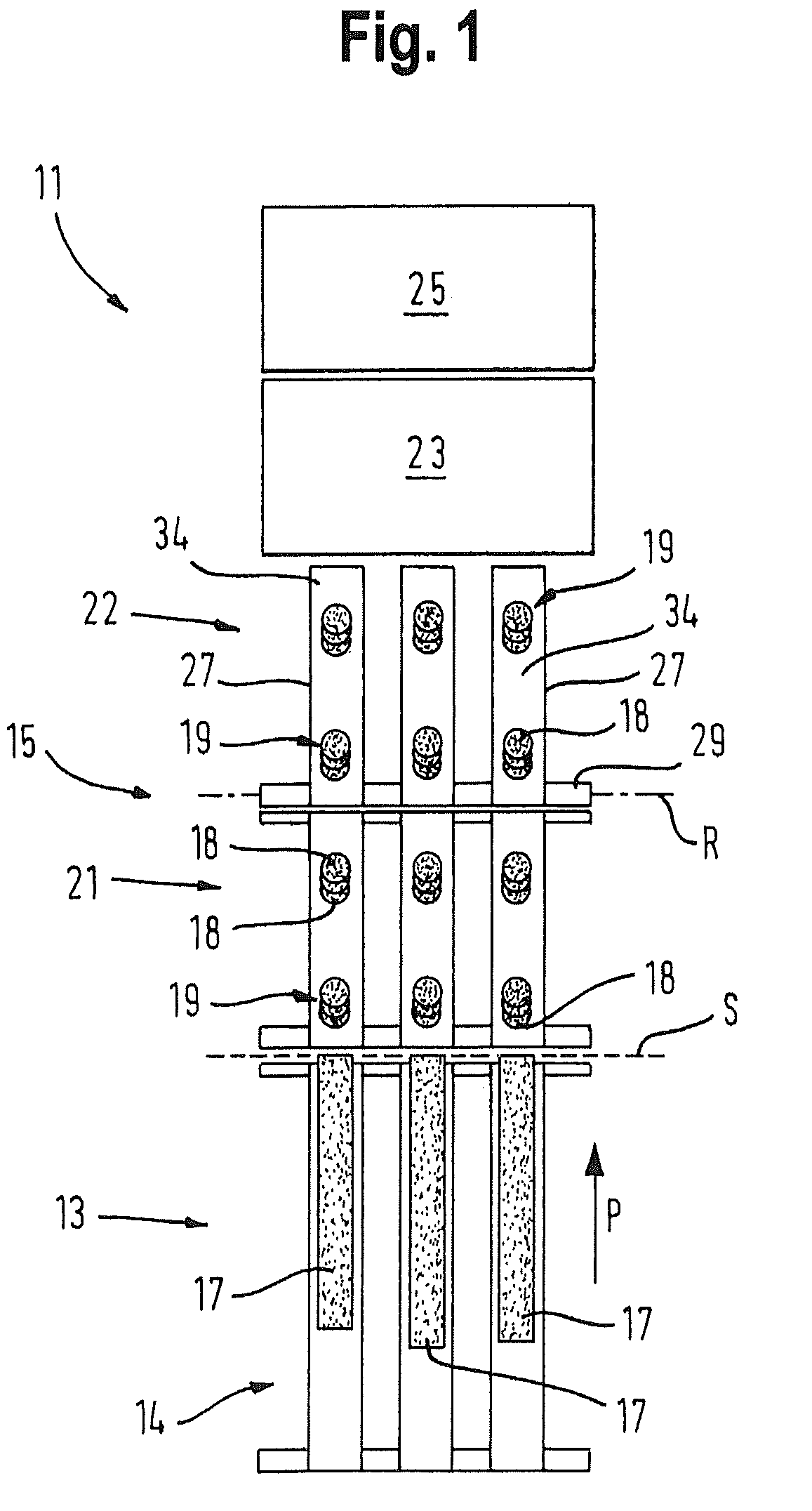
[0024]FIG. 1 shows in simplified form a production line 11 for producing packaged portions, e.g. of slices of meat, sausage or cheese. A high-performance slicer 13 of the production line 11 comprises a product supply 14 which is adapted to deliver a plurality of products 17 next to one another along a product conveying direction P to a cutting plane S in which a common cutting blade (not shown) moves, in particular rotationally and / or revolving manner. The product slices 18 cut off by the cutting blade are delivered in individual product portions 19 to a multi-lane conveyor line 15 which comprises an input conveyor 21, a sorting conveyor 22, a buffer device 23 as well as a packaging device 25. The product portions 19 are in this manner supplied to the packaging device 25, with the sorting conveyor 22 being, inter alia, able to expel portions of incorrect weight from the product flow.

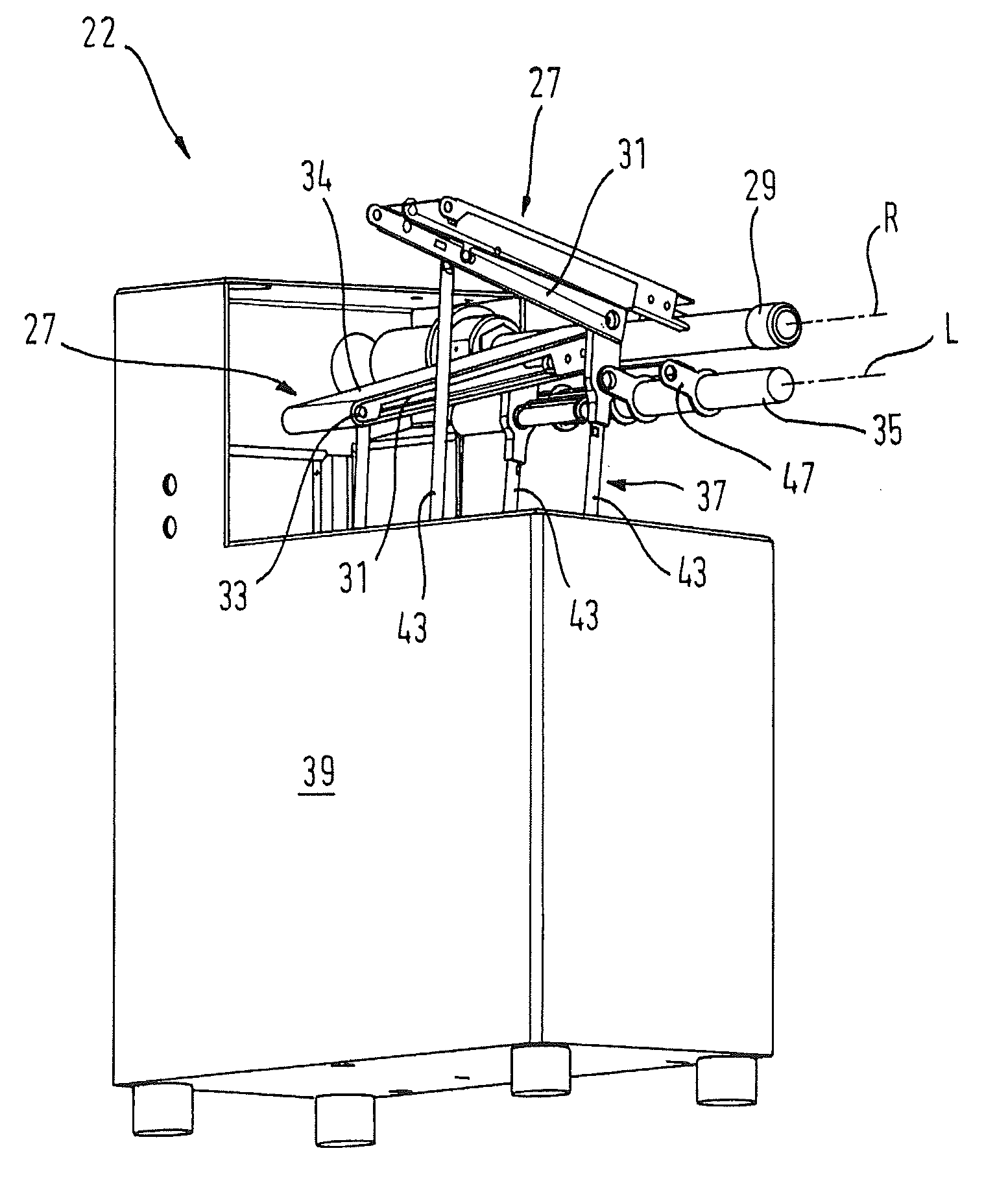
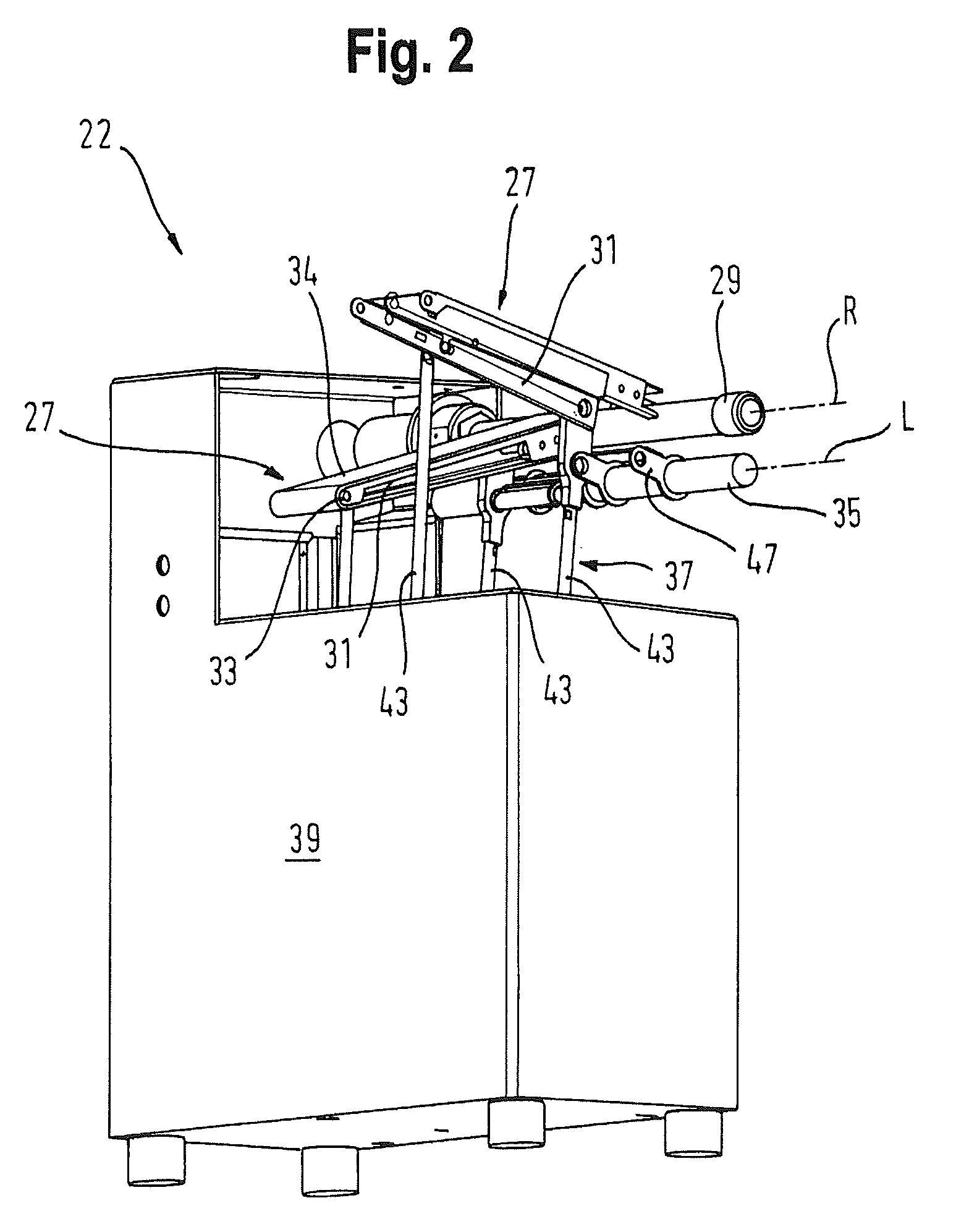
[0025]The sorting conveyor 22 will be described in more detail with reference to FIGS. 2 to 5. Accord...


PUM


Abstract

An apparatus for conveying products comprising at least one conveyor device being drivable by a drive shaft in order to supply the products to each of a plurality of output regions, wherein said conveyor device comprises a support structure which can be pivoted about an axis of rotation of said drive shaft for individually changing said output region. Said support structure is pivotably supported by a jointed arm arrangement at a support element spaced apart from said drive shaft such that, by moving said jointed arm arrangement, said support structure is pivotable about said axis of rotation of said drive shaft.

Description

CROSS-REFERENCE TO RELATED APPLICATIONS[0001]This patent application claims the benefit of priority to German Patent Application Serial No. 102011017420.6, filed Apr. 18, 2011, which is incorporated herein by reference in its entirety.FIELD OF THE INVENTION[0002]The present invention relates to an apparatus for conveying products, in particular food products, with at least one conveyor device being drivable by a drive shaft in order to convey the products to a respective one of a plurality of output regions, wherein the conveyor device comprises a support structure which can be pivoted about an axis of rotation of the drive shaft for individually changing the output area.BACKGROUND[0003]Such an apparatus is used, for example, to transport food products such as meat, sausage or cheese in portions from a slicing device, such as a high-performance slicer, to a packaging machine. By changing the output region, product portions of incorrect weight can be expelled from the product flow as...

Claims


Application Information

Patent Timeline
Patent Type & Authority Patents(United States)
IPC IPC(8): B65G21/12B65G47/64
CPCB65G47/647B65G21/12
Inventor BAUER, SIGFRID
Owner WEBER MASCHENBAU
Why Eureka
Try Eureka