Trainable multi-mode floor cleaning device

a floor cleaning and multi-mode technology, applied in the direction of floor surfacing/polishing machines, cleaning filter means, program control, etc., can solve the problems of many autonomous floor cleaning devices not being able to traverse stairs or discontinuities common to many living environments, and devices are not without their respective drawbacks

Active Publication Date: 2014-07-08
SC JOHNSON & SON INC
View PDF333 Cites 64 Cited by
  • Summary
  • Abstract
  • Description
  • Claims
  • Application Information

AI Technical Summary

Problems solved by technology

However, such devices are not without their respective drawbacks.
One drawback of such a device can be attributed to the navigation of such devices.
Because many floor cleaning devices are designed to randomly traverse the area to be cleaned, many such systems are provided with generally complex navigation systems that include collision avoidance features, device position monitoring systems, and ledge avoidance guidance.
The device position monitoring systems also complicate device construction and implementation.
Many autonomous floor cleaning devices are simply unable to traverse stairs or elevational discontinuities common to many living environments.
Each of the navigation and guidance solutions discussed above complicates the construction of the respective autonomous floor device and / or use or integration of the floor cleaning device relative to the intended operating environment.
Furthermore, where such systems require the movable device to support the operation of the necessary detectors, sensors, and the like, such systems increase the weight associated with the moving portion of the cleaning system as well as consume the limited energy resources that must be supported by the autonomous device.
Furthermore, more sophisticated navigational controls increase manufacturing and operational demands associated with providing such systems.
Accordingly, although such systems improve user confidence that the device will be able to maintain its autonomous nature for a longer duration and / or for a number of cleaning cycles without user interaction, such systems also substantially complicate the construction of the device and reduce the amount of energy that is available for consumption by the cleaning systems.
Although such systems improve the utility of autonomous floor cleaning devices, such devices are not without their respective drawbacks.
For instance, during autonomous operation, cleaning devices equipped with a rotatable brush or “beater bar” can occasionally snag or become entangled with an end of a thread or fray commonly found near the perimeter of the carpet of a room.
Such occurrence presents the opportunity that the cleaner will unravel the thread into the field of the carpet causing an unacceptable blemish.
Further, for those systems equipped with multiple cleaning modes, such as a rotating brush for use with carpet and a cleaning pad for use with floors, it is commonly undesirable to have both of such cleaning systems concurrently engaged.
As is commonly understood, operating a rotatable brush over wood covered floors can mar or undesirably affect the finish of the floor if debris becomes entangled in the rotatable brush.
Similarly, passing a cleaning cloth over a carpeted floor can result in unnecessary use and / or wear of the cleaning cloth and / or floor carpet as well as premature draining of the power source of the autonomous cleaning device.
Furthermore, although a number of known devices have multiple cleaning modes, such devices are generally not specific to the particular composition of the material of the floor being cleaned.
That is, such devices are commonly limited with respect to cleaning carpeted floors as compared to solid surface floors.
Simply, such devices commonly leave many areas that are simply not adequately cleanable with a given device configuration.
Providing multiple floor cleaning devices unnecessarily increases user costs whereas manually configuring such devices for operation over different flooring materials detracts from the benefits associated with the autonomous nature of such systems.

Method used


Image

  • Trainable multi-mode floor cleaning device
  • Trainable multi-mode floor cleaning device
  • Trainable multi-mode floor cleaning device

Examples


Embodiment Construction

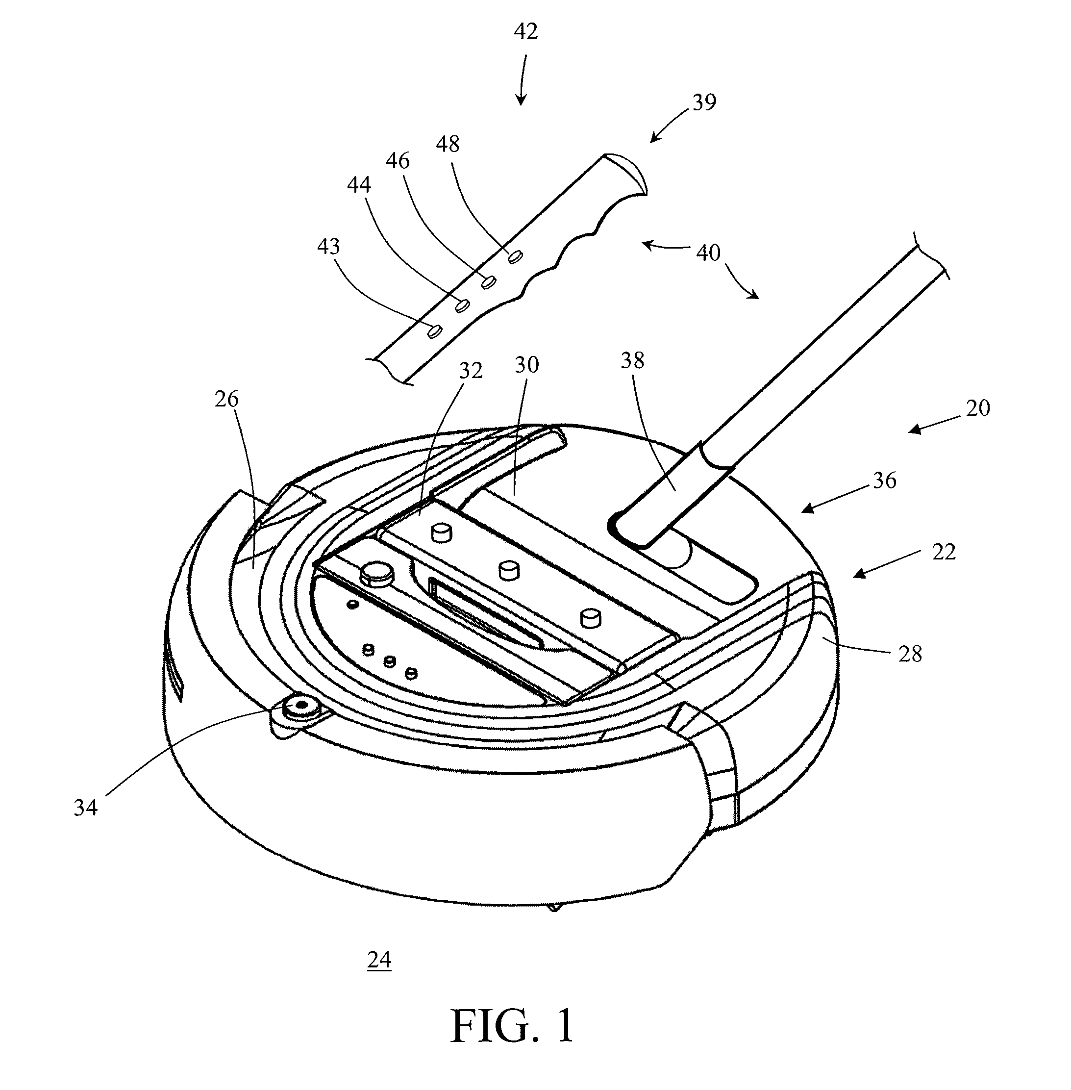
[0045]FIG. 1 shows an autonomous floor cleaning system 20 according to the present invention. As discussed below, floor cleaning system 20 is constructed to perform autonomous or independent floor cleaning operations. As mentioned above, other cleaning systems / devices and / or floor cleaning systems / devices are disclosed in U.S. Pat. Nos. 7,389,166 and 7,578,020; United States Patent Application Publication Nos. 2004 / 0031121, 2004 / 0031113, 2004 / 0031111, 2005 / 0229340, 2006 / 0288519, 2006 / 0293794, 2008 / 0188984; and U.S. Provisional Patent Application Ser. Nos. 60 / 948,676, 60 / 908,312, and 60 / 946,848; the disclosures of each of which are hereby expressly incorporated. It is appreciated that the autonomous device disclosed herein has applications beyond floor cleaning such as lawn care and toys and / or entertainment purposes. In an exemplary embodiment, autonomous device 22 is configured to perform floor cleaning operations. In a more preferred embodiment of the invention, device 22 is confi...


PUM

PropertyMeasurementUnit
areaaaaaaaaaaa
structuresaaaaaaaaaa
weightaaaaaaaaaa

Abstract

A floor cleaning device that is manually trainable for subsequent automatic operation. Prior to automatic operation, a user trains the cleaning device by manually manipulating the device through one or more desired cleaning paths. After training of the device, the device is configured to automatically initiate subsequent cleaning operations in accordance with the trained routine(s). Preferably, the training routine includes user specification of one of a number of cleaning modalities that are supported by the flooring cleaning device. In addition to automatic navigation, the floor cleaning device is configured to initiate a desired cleaning modality as a function of the device's position with respect to one or more of the trained routine(s).

Description

CROSS REFERENCE TO RELATED APPLICATIONS[0001]This application claims priority to U.S. Provisional Patent Application Ser. No. 61 / 186,222 filed on Jun. 11, 2009 titled “Trainable Multi-Mode Floor Cleaning Device” the disclosure of which is incorporated herein.BACKGROUND OF THE INVENTION[0002]1. Field of the Invention[0003]The present invention relates to autonomous cleaning systems, and more particularly, to autonomous floor cleaning devices that are operable in a number of cleaning “modes” and are trainable such that users can specify a desired cleaning path for the floor cleaning device.[0004]2. Discussion of the Related Art[0005]Autonomous floor cleaning devices have gained in popularity and utility in recent years. The various benefits of having a cleaning device that will automatically initiate and complete a cleaning routine without continuous user interaction have increased the common use of such devices. However, such devices are not without their respective drawbacks.[0006]O...

Claims


Application Information

Patent Timeline
Patent Type & Authority Patents(United States)
IPC IPC(8): G05B19/18A47L5/28G05B15/02G05D1/02
CPCG05D1/0272A47L5/28A47L2201/04G05B15/02G05B2219/45098G05D1/0221G05D1/0225G05D1/0242G05D1/0255G05D2201/0203
Inventor KNOPOW, JEREMY F.CURTIS, DAVIDCARTER, JR., EVERETT F.LARSON, TEDALLEN, BOB
Owner SC JOHNSON & SON INC
Why Eureka
Try Eureka