Aluminium alloy truss structure

a technology of aluminum alloy and trusses, which is applied in the direction of girders, joists, portal frames, etc., can solve the problems of unsafe and unreliable load bearing structures in civil engineering works, and prone to local buckling of proportions, so as to reduce the own weight of buildings, high strength, and corrosion resistance performance

Inactive Publication Date: 2014-07-22
LIN JUAN +1
View PDF13 Cites 5 Cited by
  • Summary
  • Abstract
  • Description
  • Claims
  • Application Information

AI Technical Summary

Benefits of technology

[0004]The objective of this invention is to provide an aluminum alloy truss structure. The truss structure of this invention involves the use of mating tenon-mortise groove connection nodes or implanted plate type body-shaped connection nodes. All the members of the truss structure are made from aluminum alloy. And all the members meeting at the connection nodes are fastened together using bolts or riveting bolts. This invention contributes to greatly reduced own weight of buildings and a save of materials for columns and foundation that serve to support the truss structure. Moreover, this invention allows rapid assembling of members at construction site and is particularly advantageous to cut the construction costs, and can further improve the earthquake resistant performance of structures. In addition, the aluminum alloy materials almost require no maintenance throughout their service life, thereby making it possible for a project to function for more than one hundred years. The trusses can have an either large or small span, and are widely employed in civil engineering works such as large-span factory buildings, exhibition halls, stadiums and bridges etc.

Problems solved by technology

Unfortunately, for load bearing structures in civil engineering works (especially large-span grid structures, for example), the connection node arrangement in accordance with the said application has deficiencies in that the solid portions at the bottom of the grooves are excessively thin and the shear pin holes in the groove walls have to be disposed at relatively high locations due to the constraints of connection requirements, and, consequently, there is a potential risk that these portions are susceptible to local buckling under the effects of the pressure rods in the civil engineering works.
Moreover, the application of screws to connect the members would give rise to unreliable load bearing structures in civil engineering works.
For ease of assembling, one would have to resort to shear pins and retaining parts which are used to fasten the members, which, however, are unsafe and unreliable for load bearing structures in civil engineering works either.
Thus, the ability of the “connector” to carry the internal forces of connection nodes of load bearing structures in civil engineering works is obviously insufficient.

Method used


Image

  • Aluminium alloy truss structure
  • Aluminium alloy truss structure
  • Aluminium alloy truss structure

Examples


embodiment 1

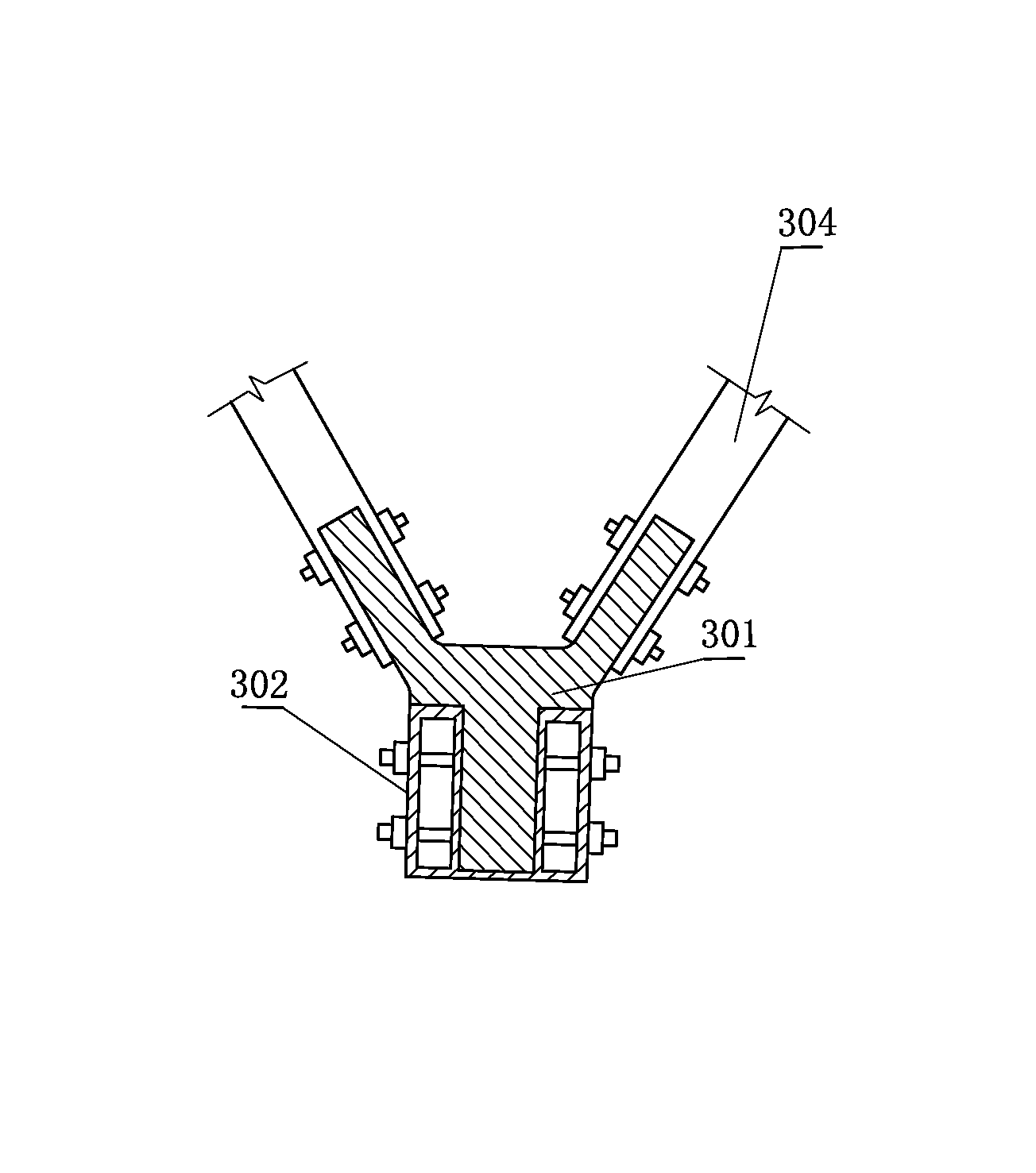
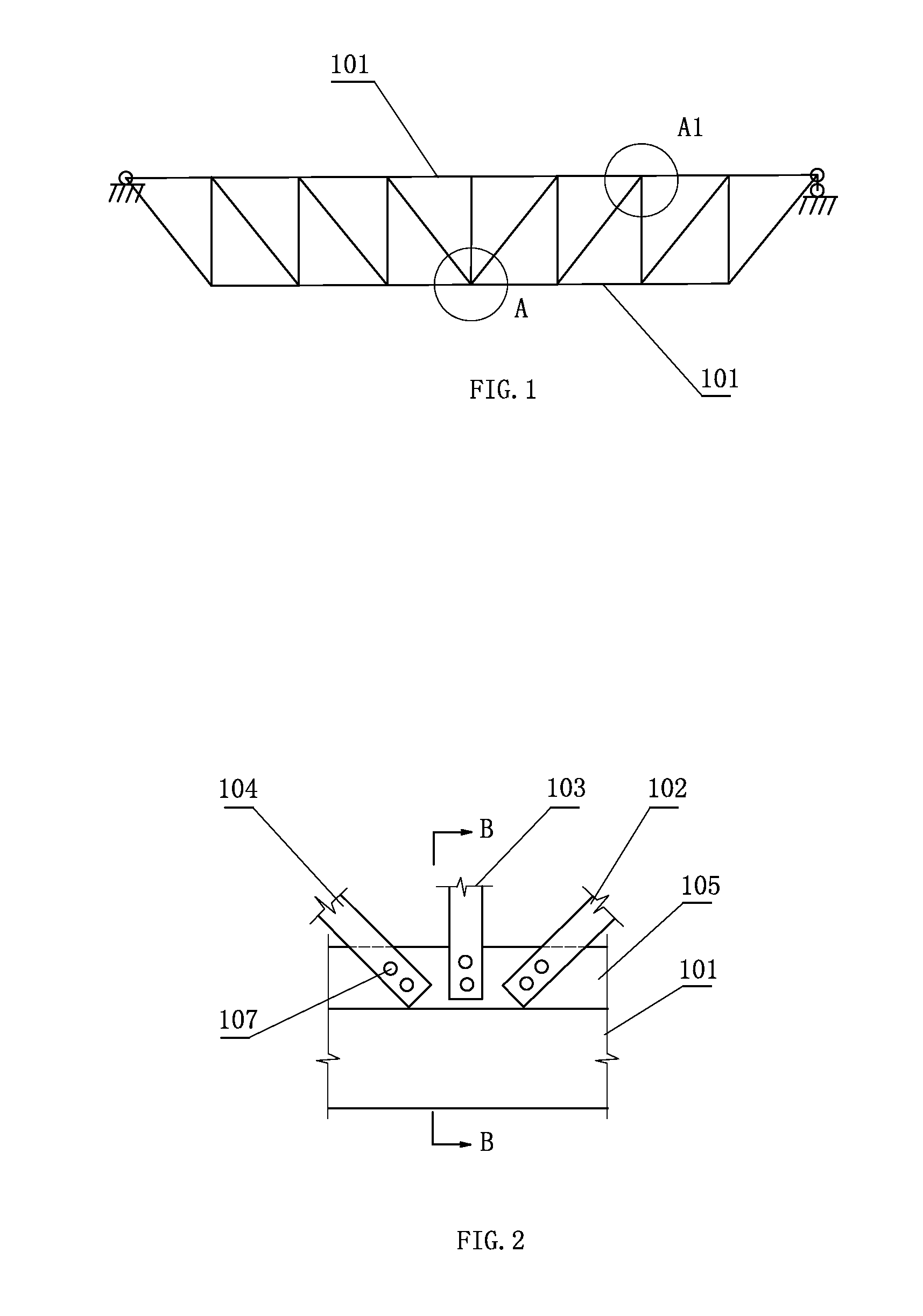
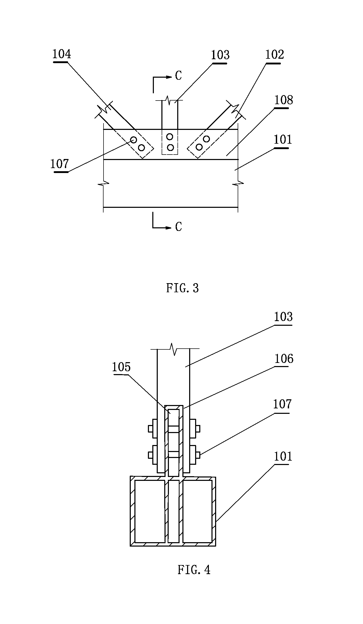
[0057]Referring to FIGS. 1-5, there is illustrated an aluminum alloy truss structure, comprising upper chord members, lower chord members, web members and all connection nodes by which the members are interconnected using riveting bolts; all members of the truss are made from aluminum alloy materials; the chord members and web members are interconnected using tenons and mortise grooves that mate with each other, each of the chord members being provided with a tenon plate at the end adjacent to the web members, each of the web members being correspondingly provided with a mortise groove at either end thereof to mate with the tenon plate, and the tenon plate on the chord members being implanted into the mortise groove on the web members; or, alternatively, each of the chord members being provided with a mortise groove at the end adjacent to the web members, each of the web members being correspondingly provided with a tenon at either end thereof to mate with the mortise groove, either...

embodiment 2

[0061]Referring to FIGS. 6-8, there is illustrated an truss structure, comprising a plate-shaped connection node plate and chord members and web members of aluminum alloy materials respectively connecting therewith, all the aluminum alloy members of the truss each having a groove made at either end thereof, the plate-shaped connection node plate being implanted into the grooves at the respective ends of all members that meet at a node and fastened together with the members using bolts or riveting bolts.

[0062]Referring to FIG. 6, this embodiment deals with a planar truss structure, comprising a plurality of connection notes D and D1 which are of the same structure. A implanted plate type structure is disposed respectively at the connection nodes. All the connection node plates and all truss members are fabricated using aluminum alloy materials. Each member is provided at either end (two ends in total) thereof with an opening (groove). Each connection node plate is implanted into the ...

embodiment 3

[0065]The truss structure in accordance with this embodiment comprises all body-shaped connection node bodies of the space truss and all aluminum alloy members of the space truss that intersect at the respective connection nodes and are interconnected with the respective connection node bodies, all the aluminum alloy members of the space truss each having an groove made at either end thereof to receive an limb plate of a connection node body that is implanted into the groove, each body-shaped connection node body being provided with three limb plates, respectively referred to as U, V and W, along X, Y and Z direction of the space truss, the three limb plates being respectively implanted into the grooves at the ends of all members that respectively intersect along X, Y and Z direction at a node and fastened together with the members using bolts or riveting bolts.

[0066]Referring to FIGS. 9-14, there is illustrated an aluminum alloy truss structure involving the use of implanted plate ...


PUM


Abstract

An aluminum alloy truss structure, comprising upper chord members, lower chord members, web members and all connection nodes by which the members are connected using riveting bolts, the chord members and web members being interconnected using tenons and mortise grooves that mate with each other respectively, each of the chord members being provided with a tenon plate at the end adjacent to the respective web members, each of the web members being correspondingly provided with a mortise groove at either end thereof, and the tenon plate on the chord members being implanted into the mortise groove on the web members; or, alternatively, each of the chord members being provided with a mortise groove at the end adjacent to the respective web members, each of the web members being correspondingly provided at either end thereof with a tenon that is to mate with the mortise groove.

Description

CROSS-REFERENCE TO RELATED APPLICATION[0001]This application claims the priority benefit of China application No. 201110088373.5, filed on Apr. 11, 2011, application No. 201110098178.0, filed on Apr. 20, 2011, application No. 201110112365.X, filed on May 3, 2011, application No. 201110129530.2, filed on May 19, 2011 and application No. 201110164626.2, filed on Jun. 20, 2011. The contents of these prior applications are hereby incorporated by reference in their entirety.FIELD OF THE INVENTION[0002]The present invention relates to an aluminium alloy truss structure. The truss structure of this invention involves the use of mating tenon-mortise groove connection nodes or implanted plate type body-shaped connection nodes. All the members of the truss structure are made from aluminum alloy. And all the members meeting at the connection nodes are fastened using bolts or riveting bolts.DESCRIPTIONS OF THE RELATED ART[0003]China Patent Application Serial No. 200780039151.6 discloses a space...

Claims


Application Information

Patent Timeline
Patent Type & Authority Patents(United States)
IPC IPC(8): E04B1/18E04B1/19
CPCE04B2001/1933E04C3/40E04B2001/1984E04C2003/0491E04C3/08E04B1/19E04C2003/0495E04B2001/1927E04B2001/1918E04B1/1903
Inventor LIN, JUANLIANG, KUN
Owner LIN JUAN
Why Eureka
Try Eureka