Connector

a technology of connecting rods and connectors, applied in the direction of securing/insulating coupling contact members, coupling device connections, electrical devices, etc., can solve the problems of reducing the reliability of the front end portion of the terminal fitting, and achieve the reduction of the overall size of the connector, the reduction of the height difference, and the reduction of the size of the terminal fitting.

Inactive Publication Date: 2014-07-22
SUMITOMO WIRING SYST LTD
View PDF13 Cites 8 Cited by
  • Summary
  • Abstract
  • Description
  • Claims
  • Application Information

AI Technical Summary

Benefits of technology

[0011]Moreover, since the necessity to form a guide slope that is inclined with respect to the insertion direction of the terminal fitting in the receiving face of the front member is eliminated, a long formation region for the receiving face can be ensured in the insertion direction of the terminal fitting, and the front end portion of the angular tube portion can be reliably supported by the front member.
[0013]A displacement restricting portion is formed in at least one of the housing and the front member, the displacement restricting portion being elastically deformed in the state in which the front member is attached to the housing, thereby restricting relative displacement between the housing and the front member in a direction intersecting the insertion direction of the terminal fitting.
[0014]This has the following advantages. In a state in which the front member is attached to the housing, if there is play between the housing and the front member in a direction intersecting the insertion direction of the terminal fitting, it is necessary to absorb the play by increasing the protruding length of the guide projection so that a large difference in height between the receiving face and the opposing outer face is ensured in a height direction relative to the bottom face of the guide recess. In this regard, when the displacement restricting portion is elastically deformed in the state in which the front member is attached to the housing, the displacement restricting portion restricts relative displacement between the housing and the front member in a direction intersecting the insertion direction of the terminal fitting, so that the necessity to ensure a large protruding length of the guide projection in order to absorb play is eliminated. Thus, the size of the terminal fitting can be reduced, and therefore the overall size of the connector can be reduced.

Problems solved by technology

However, this guide slope merely guides the front end portion of the terminal fitting to the back (front) of the terminal holding chamber, and does not have a function of supporting the front end portion of the terminal fitting that is properly inserted in the terminal holding chamber.
This means that as a result of forming the guide slope, the area of a portion of the inner wall faces of the terminal holding chamber that supports the front end portion of the terminal fitting is reduced, and thus there is the problem of a decrease in the reliability of the function of supporting the front end portion of the terminal fitting.

Method used


Image

  • Connector
  • Connector
  • Connector

Examples


embodiment 1

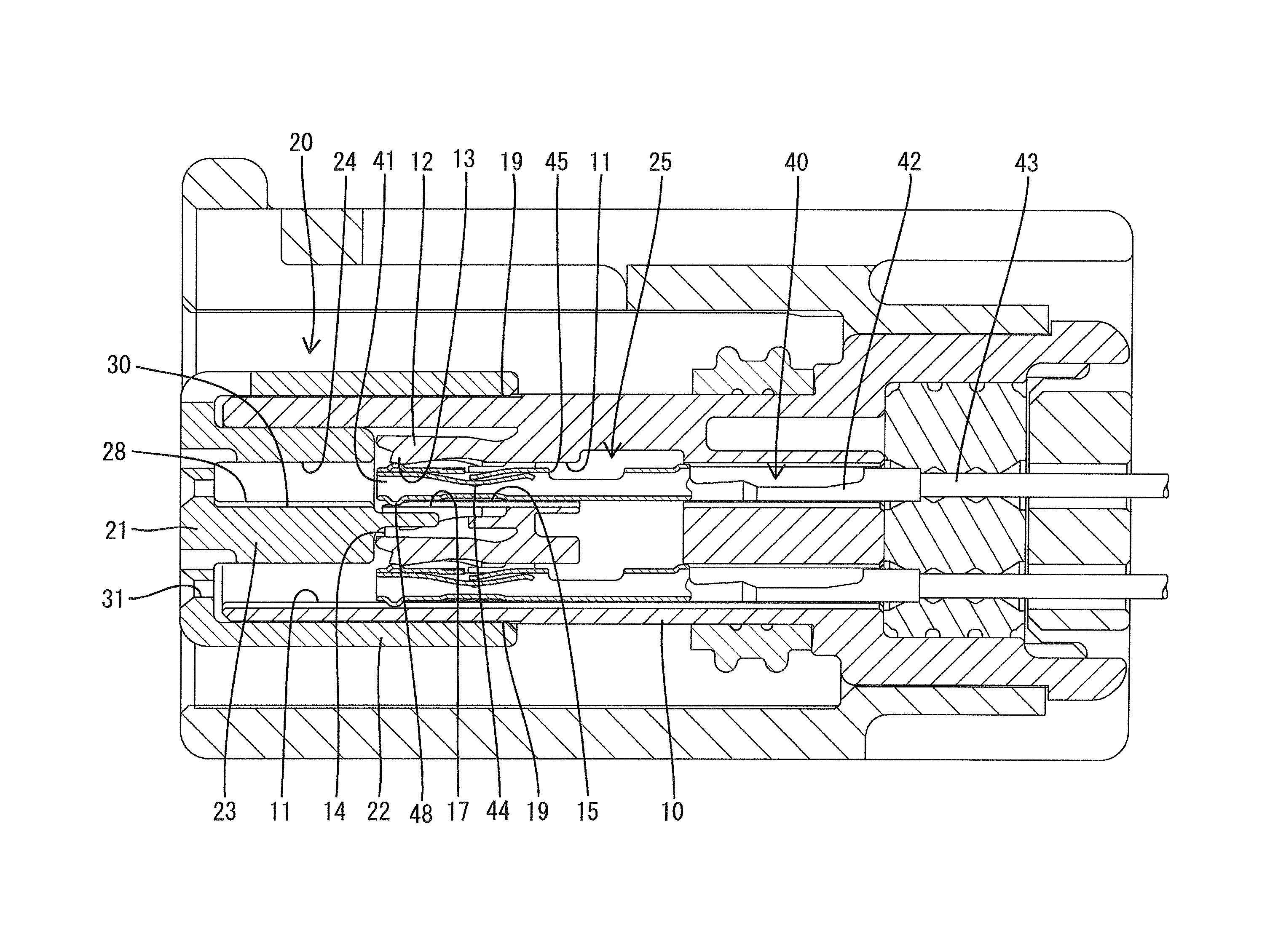
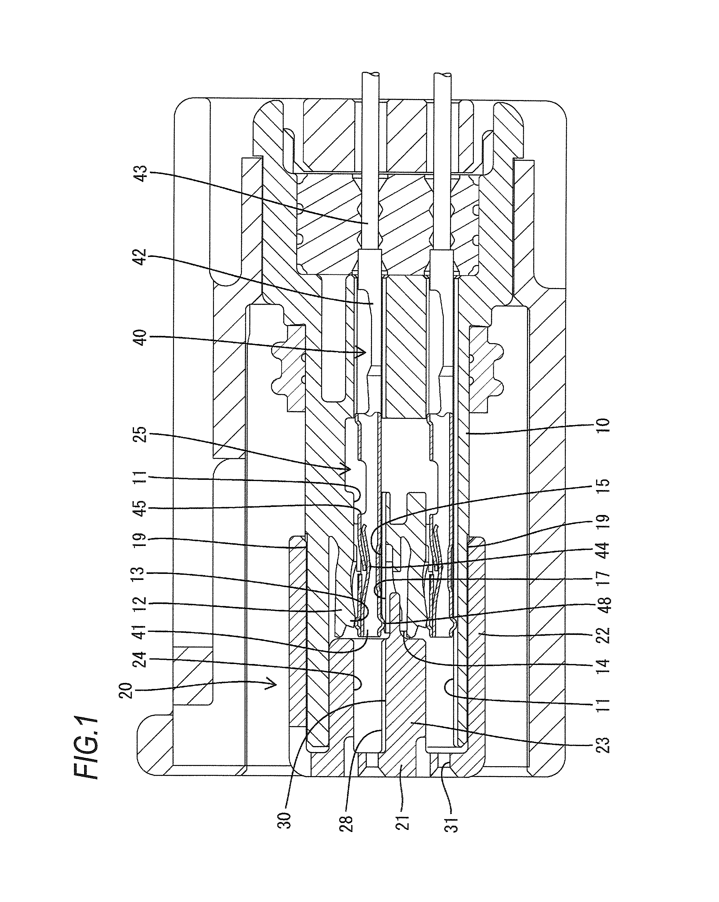
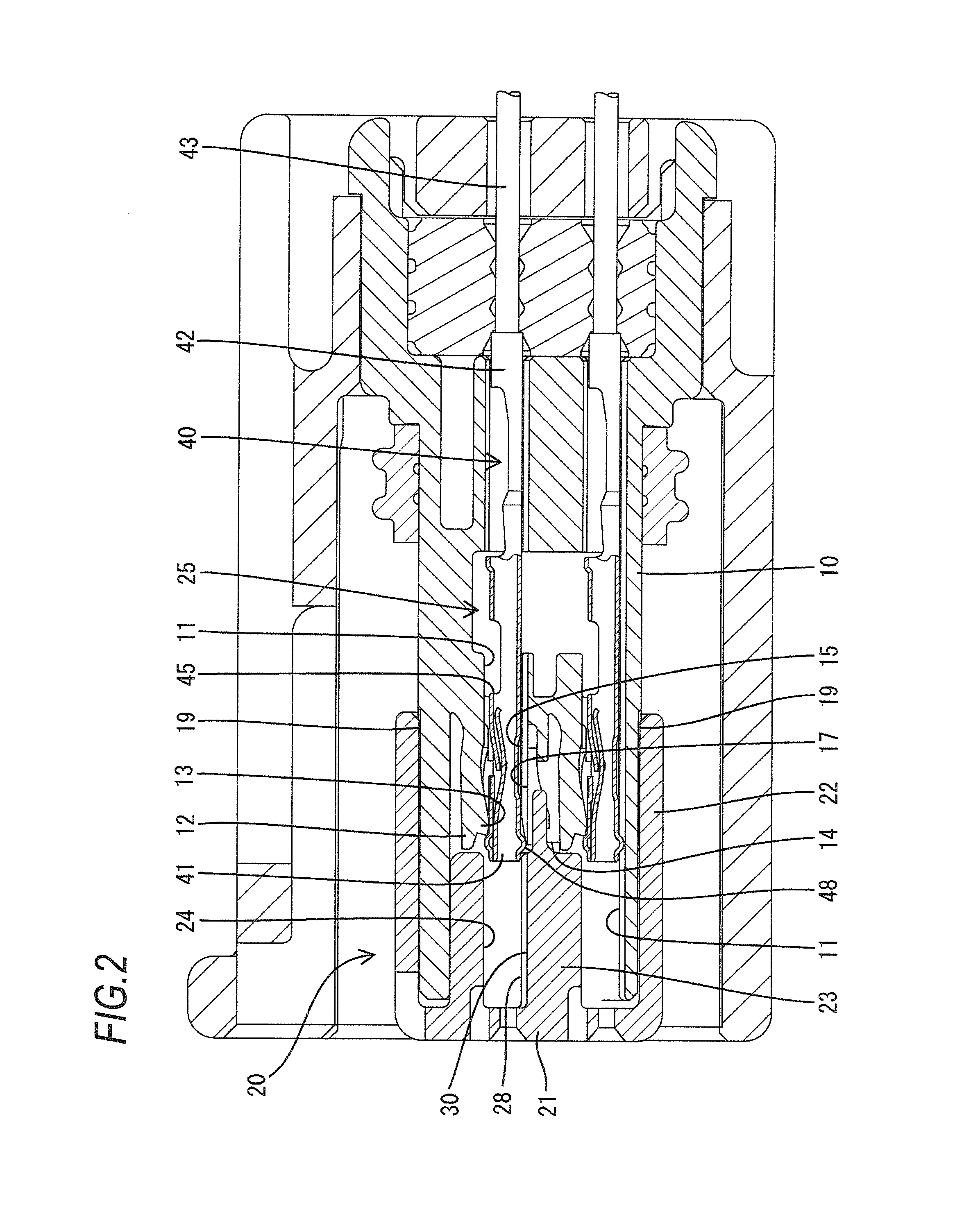
[0028]Hereinafter, Embodiment 1 in which the present invention is embodied will be described with reference to FIGS. 1 to 13. A connector of the present embodiment includes a housing 10, a front member 20 attached to the housing 10 from ahead (the left-hand side in FIGS. 1 to 3), and a plurality of terminal fittings 40 inserted into the housing 10 from behind. It should be noted that in the following description, “direction parallel to the insertion direction of the terminal fittings 40” and “front-rear direction” are used synonymously. Also, the insertion direction of the terminal fittings 40 may be simply referred to as “terminal insertion direction”.

[0029]The housing 10 is made of a synthetic resin. A plurality of terminal accommodation chambers 11 penetrating the housing 10 in the front-rear direction are formed in the housing 10. As shown in FIGS. 8 and 9, the plurality of terminal accommodation chambers 11 are divided into three rows in the vertical direction and arranged in t...


PUM


Abstract

A terminal fitting is inserted into a terminal holding chamber of a front member. A guide recess is in an opposing wall face opposing a lance, of inner faces of a terminal accommodation chamber, an escape recess continuous with the guide recess is in a receiving face of the terminal holding chamber, a guide projection protruding from a position rearward of the front end of an angular tube portion and making sliding contact with a bottom face of the guide recess is in an opposing outer face of the angular tube portion. The length from the guide projection to the front end of the angular tube portion is larger than the distance between the front end of the guide recess and the rear end of the receiving face, and the height of the receiving face relative to the bottom face is smaller than the height of the opposing outer face.

Description

CROSS-REFERENCE TO RELATED APPLICATION[0001]This application is based on and claims priority under 35 USC 119 from Japanese Patent Application No. 2010-195934 filed Sep. 1, 2010.BACKGROUND OF THE INVENTION[0002]1. Field of the Invention[0003]The present invention relates to a connector.[0004]2. Description of the Related Art[0005]Japanese Patent No. 3491751 discloses a connector including a housing in which a terminal accommodation chamber is formed and a front member attached to the housing. In a state in which the front member is attached to the housing, a terminal holding chamber in the recess form in a rear face of the front member is located so as to correspond to an opening at a front end of the terminal accommodation chamber, and a terminal fitting is inserted into a cavity constituted by the terminal accommodation chamber and the terminal holding chamber from behind. In the process of inserting the terminal fitting, a lance formed along an inner wall of the terminal accommod...

Claims


Application Information

Patent Timeline
Patent Type & Authority Patents(United States)
IPC IPC(8): H01R13/40H01R13/422H01R13/436H01R13/516
CPCH01R13/516H01R13/4223H01R13/4364
Inventor SUZUKI, MASAKAZU
Owner SUMITOMO WIRING SYST LTD
Why Eureka
Try Eureka