Transferring shuttle for three dimensional automated warehouse

a technology of automated warehouse and transfer shuttle, which is applied in the direction of transportation and packaging, loading/unloading, storage devices, etc., can solve the problems of affecting the end-use storage capacity, increasing manufacturing costs,

Active Publication Date: 2014-07-29
DEMATIC
View PDF32 Cites 82 Cited by
  • Summary
  • Abstract
  • Description
  • Claims
  • Application Information

AI Technical Summary

Benefits of technology

[0013]The package can be transferred in and out by placing the terminal fingers in the extended position so that the left and right end surfaces of the package are pushed by the fingers. In the prior art, the packages are pushed by the terminal fingers on the rail; however, in an embodiment of the present invention, having the fingers further inside pushes the package while reducing the overlap between the rails and makes it possible to transfer the package into a deeper position in the layered stacked rack. Thus, it becomes possible to contain more packages in a layered stacked rack. More specifically, two packages in a row (front and back with respect to the direction of the movement of the packages) can be placed with a three-rail elastic mechanism. Also, since there is no need to increase the number of the rails in the elastic mechanism, there is no requirement for extra clearance between the packages. Furthermore, the addition of the inner fingers allows the existing profile (of the steel shape) to be maintained, thereby preventing an increase in production cost.
[0014]In one embodiment, there may be two sets of inner fingers. By having two sets of inner fingers, three packages can be handled simultaneously, depending on the size and shape of the packages (as shown in FIG. 7C). Furthermore, the inner fingers may be positioned such that sufficient space exists for placing a package between an inner finger and the terminal finger further away from the inner finger, or between the other inner finger and the other terminal finger. By allowing the terminal finger to travel a distance exceeding the length of two packages placed next to each other in the layered stacked rack adjacent to the terminal finger, it becomes possible to place two packages in a row (front and back).
[0016]Furthermore, the method of actuation of the first sliding rail may be comprised of an endless belt with teeth on the exterior perimeter and a rack mounted on the first sliding rail which meshes with the teeth on the exterior surface. By using the belt with external teeth, rather than pinions, it becomes possible to extend the first sliding rail beyond the fixed rail.

Problems solved by technology

Increasing the number of wearable members such as sliding rails may lead to breakage.
Also, as the device structure becomes more complex, commonization of purchased parts becomes difficult, and the economy of scale becomes less viable, leading to an increase in manufacturing cost.
Furthermore, the increase in the thickness of the elastic mechanism necessitates the designing of sufficient space for the sliding rail above the layered stacked rack and increases the needed clearance between the packages, hindering the increase of the storage capacity in the end.

Method used


Image

  • Transferring shuttle for three dimensional automated warehouse
  • Transferring shuttle for three dimensional automated warehouse
  • Transferring shuttle for three dimensional automated warehouse

Examples


example 1

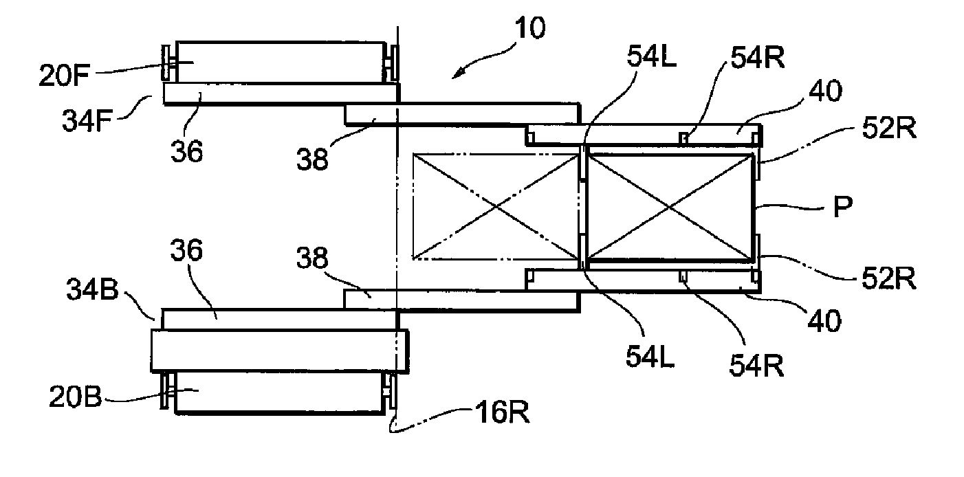
[0042]If the relaying station is on the right hand side of FIG. 4, and the storage location in the rack is on the right hand side, use the outer (terminal) finger to pull in the package.

example 2

[0043]If the relaying station is on the right hand side of FIG. 4, and the storage location in the rack is on the left hand side, use the inner finger to pull in the package.

[0044]It should be obvious that the cases where the relaying station is on the left side can be effectively dealt with by going through a similar (symmetric) set of motions.

[0045]If the storage location is close (to the transferring shuttle), either the outer (terminal) finger or the inner finger can be used in the loading of the package P to avoid the procedure described above in paragraph [0037].

[0046]On the other hand, when the package P is stored at the close location and is pulled out of the layered stacked rack on the right hand side 16R and onto the transferring shuttle 10, any of the two inner fingers 54L or 54R, or the outer (terminal) fingers 52R can be used for retrieving the package P. In other words, starting from the package location shown in broken lines in FIG. 4B, the elastic mechanisms 34F and ...


PUM


Abstract

A transferring shuttle, which transfers package(s) between a pair of layered stacked racks in a three dimensional automated warehouse, includes a mobile platform which runs between the stacked racks; elastic mechanisms, which include telescoping rails that extend into the stacked racks and surround a package; and terminal fingers placed at the ends of the rails, which can move between an extended position, which allows the package to be engaged and a contracted position. The rails also contain inner fingers between the terminal fingers. The inner fingers can push the package further into the stacked rack than previously possible.

Description

CROSS-REFERENCE TO RELATED APPLICATIONS[0001]This patent is a national stage filing under 35 U.S.C. §371 of international application Ser. No. PCT / JP2008 / 069464 filed in the Japanese Receiving Office on Oct. 27, 2008, the complete disclosure of which is hereby incorporated herein by reference.BACKGROUND OF THE INVENTION[0002]1. Technical Area[0003]This patent relates to a three-dimensional automated warehouse with at least one pair of layered stacked racks, and more particularly to transferring shuttles which are placed on every layer, or on every few layers, of the stack of racks, and which run in a horizontal direction and transfers package(s) to and from the layered stacked racks.[0004]2. Technical Background[0005]A known example of a three dimensional warehouse is described in Japanese Patent Disclosure Heisei 8-324721. The three dimensional warehouse described in this Patent Disclosure is comprised of at least one pair of left and right layered stacks of racks, each containing ...

Claims


Application Information

Patent Timeline
Patent Type & Authority Patents(United States)
IPC IPC(8): B65G1/04
CPCB65G1/0435B65G1/0492B65G1/12B65G1/04
Inventor YAMASHITA, SHIN
Owner DEMATIC
Why Eureka
Try Eureka