Table arrangement

a table and arrangement technology, applied in the field of table arrangements, can solve problems such as complicated table shapes

Active Publication Date: 2015-10-08
SAFRAN SEATS GB LTD
View PDF19 Cites 23 Cited by
  • Summary
  • Abstract
  • Description
  • Claims
  • Application Information

AI Technical Summary

Benefits of technology

[0019]Preferably, the substantially perpendicular rotation axis is located at a distal portion of the first table element away from mounting to the mounting structure. This allows a large table area to be provided by the first table element, extending towards a passenger.
[0020]Preferably, the substantially perpendicular rotation axis is located at a distal portion of the second table element away from mounting to the mounting structure. This allows for the second table element to get closer to, for use by, a passenger.

Problems solved by technology

For example, if instead the table arrangement simply had an angled fold (at a suitable angle) between the first and second elements, this would provide a “square-on” table surface to the passenger but would result in a complicated table shape (when the first and second elements are folded in) to have to stow.

Method used


Image

  • Table arrangement
  • Table arrangement
  • Table arrangement

Examples


first embodiment

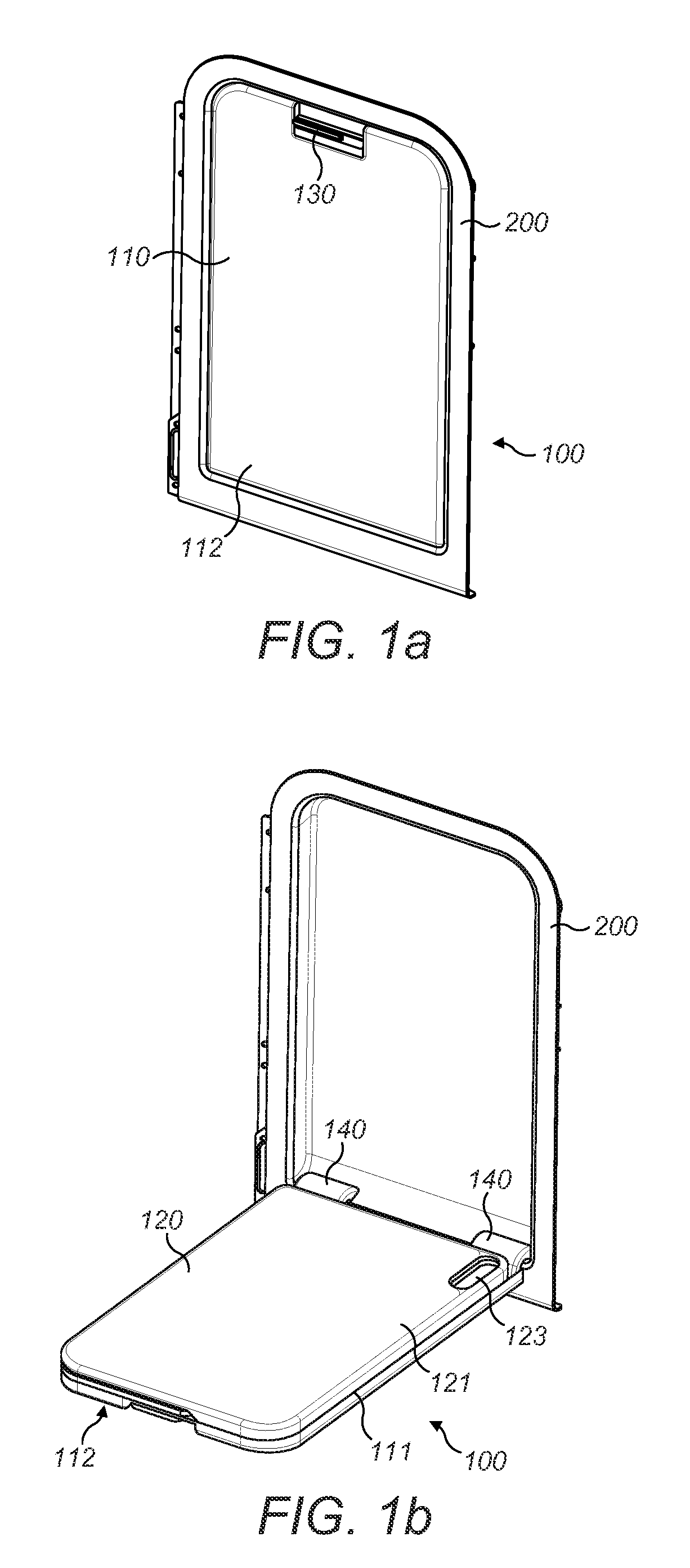
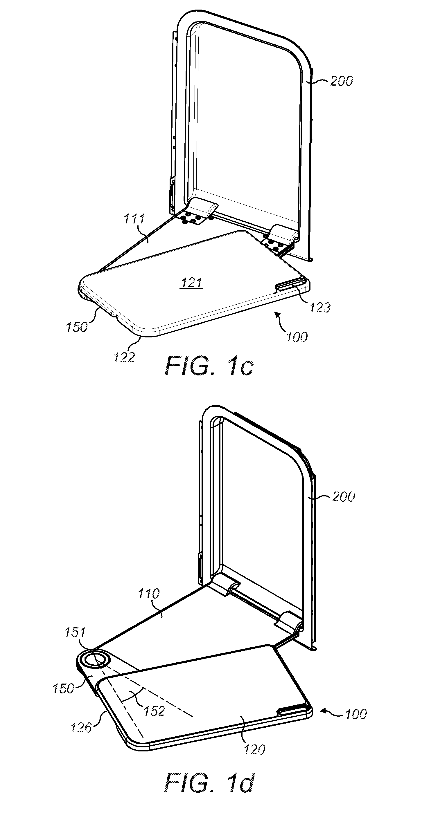
[0053]FIG. 1a shows a perspective view of a table arrangement 100 according to the invention, in a stowed position in a mounting frame 200. FIG. 1b shows a perspective view of the table arrangement 100, in a pulled down position from the mounting frame 200. FIG. 1c shows a perspective view of the table arrangement 100, in a pulled down and rotated position and FIG. 1d shows a perspective view of the table arrangement 100, in a pulled down, rotated and translated (fully deployed) position.

[0054]The table arrangement comprises a first table element 110, which is substantially rectangular in shape, with two rounded corners on an adjacent short side. The arrangement 100 also comprises a second table element 120, which has the approximate same shape and size as the first table element 110. The second table element 120 is actually slightly smaller than the first table element 110 in order to avoid a clash with hinges 140 (described later) during rotation between the stowed and pulled down...

second embodiment

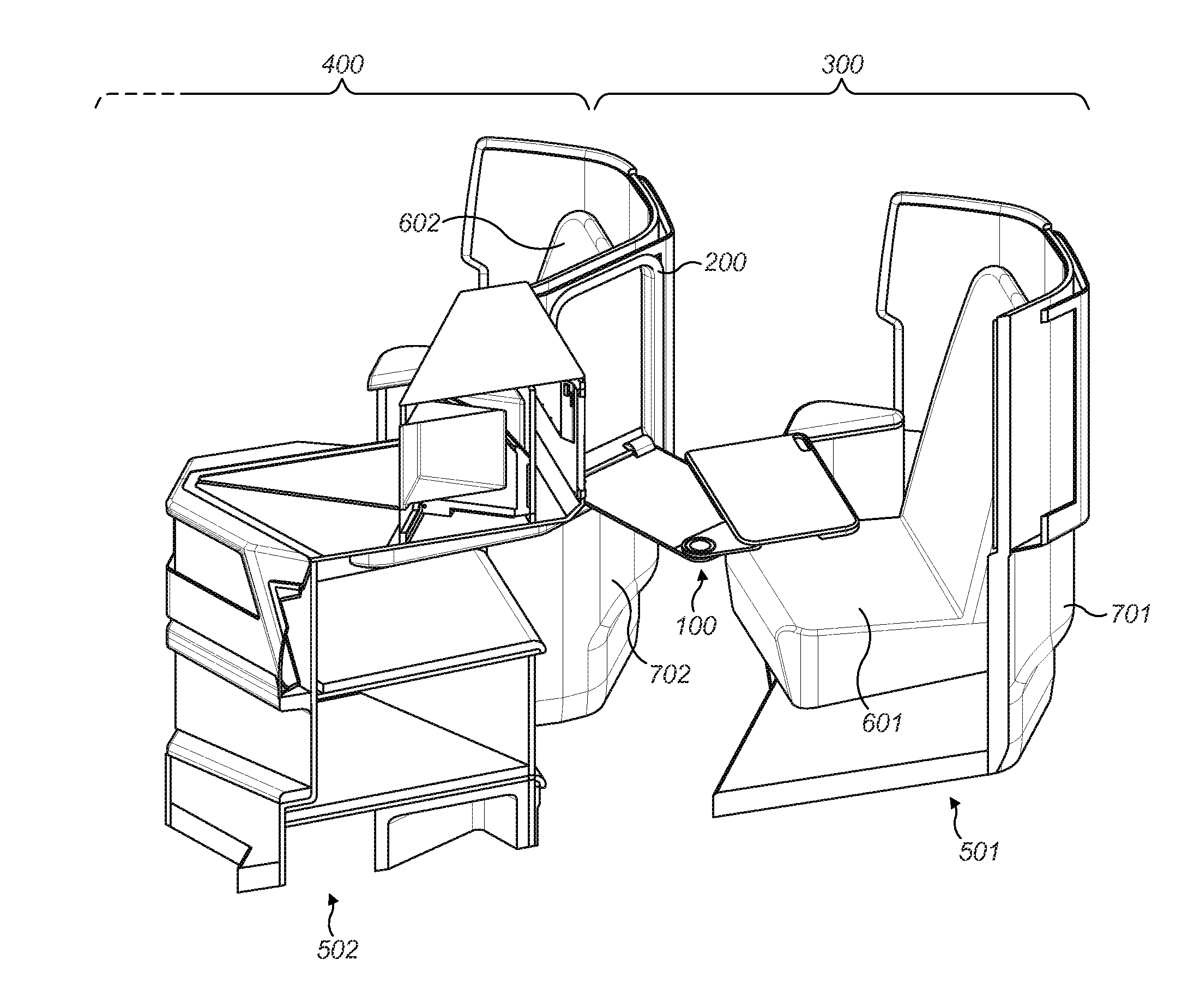
[0063]FIG. 3 shows a perspective view part of an aircraft according to the invention. Here, two aircraft seat modules are shown; a rear aircraft seat module 300 and a front aircraft seat module 400. The modules are made up of aircraft seat structures, as follows. A rear aircraft seat structure 501 comprises a console 701 with a seat 601 mounted in it. A front aircraft seat structure 502 comprises a console 702 with a seat 602 mounted in it. The rear aircraft seat module 300 is made up of the seat 601 and surrounding parts of console 701, and the rear of console 702, onto which the mounting frame 200 (and table arrangement 100) is mounted. The front aircraft seat module 400 is made up of the seat 602 and surrounding parts of console 702, and the rear of a console ahead of it (not shown), onto which a second mounting frame 200 (and table arrangement 100) would be mounted.

[0064]In FIG. 3, it can be seen that the fully deployed table arrangement (as in FIG. 1d and FIG. 2) is “square on”...


PUM


Abstract

The present invention provides a table arrangement 100 for use in an aircraft seat module, the table arrangement comprising a first table element suitable for being movably mounted to a mounting structure of the aircraft seat module, the first table element being provided with a first table surface, a second table element provided with a second table surface substantially parallel to the first table surface, wherein the second table element is mounted to the first table element, such that the second table element is moveable from a first position with respect to the first table element to a second position with respect to the first table element, the second position being transformed from the first position within the plane of the second table element. The present invention also provides an aircraft seat module, an aircraft and a method of deploying a table arrangement.

Description

CROSS-REFERENCE TO RELATED APPLICATION[0001]This application claims priority to Great Britain Application No. 1406235.0, filed Apr. 7, 2014, entitled “A Table Arrangement,” which is incorporated herein by reference in its entirety.BACKGROUND OF THE INVENTION[0002]The present invention concerns a table arrangement. More particularly, but not exclusively, this invention concerns a table arrangement for use in an aircraft seat module, the table arrangement comprising a first table element suitable for being movably mounted to a mounting structure of the aircraft seat module, the first table element being provided with a first table surface, and a second table element provided with a second table surface substantially parallel to the first table surface.[0003]The invention also concerns an aircraft seat module, and aircraft and a method of deploying a table arrangement of an aircraft seat module.[0004]There are various forms of table arrangement for an aircraft seat module.[0005]For exa...

Claims


Application Information

Patent Timeline
Patent Type & Authority Applications(United States)
IPC IPC(8): B64D11/06A47B5/04A47B13/08A47B5/00
CPCB64D11/0605A47B13/081A47B5/04A47B5/006B64D11/0638B60N3/004
Inventor GOW, ROBERTMORGAN, PAUL
Owner SAFRAN SEATS GB LTD
Why Eureka
Try Eureka