Method for sending and detecting downlink control information, sending terminal and receiving terminal
What is AI technical title?
AI technical title is built by Patsnap AI team. It summarizes the technical point description of the patent document.
A technology for controlling information and detection methods, applied in the field of communication
Active Publication Date: 2014-06-18
ZTE CORP
View PDF2 Cites 27 Cited by
Summary
Abstract
Description
Claims
Application Information
AI Technical Summary
This helps you quickly interpret patents by identifying the three key elements:
Problems solved by technology
Method used
Benefits of technology
Problems solved by technology
[0016] In view of this, the main purpose of the present invention is to provide a method for sending and detecting downlink control information, a sending end and a receiving end, so as to solve the detection problem of ePDCCH
Method used
Image
Click on the blue label to locate the original text in one second.
Reading with bidirectional positioning of images and text.
Examples
specific Embodiment approach 2
[0231] The second specific embodiment is: the starting position of the UE-specific search space corresponding to each component carrier adopts the following configuration:
[0232] The starting position on subframe k is: Y k =(A·Y k-1 ) mod D,
[0233] Among them, Y -1 =n RNTI +s×2 16 ≠0, A=39827, D=65537, Indicates rounding down, n s Indicates the slot number in a radio frame, n RNTI Indicates the corresponding RNTI, s indicates the resource set index;
specific Embodiment approach 3
[0234] The third specific embodiment is: the starting position of the UE-specific search space corresponding to each component carrier adopts the following configuration:
[0235] The starting position of resource set s on subframe k is: or or B is 1 or Y k =(A·Y k-1 )modD,
[0236] Among them, Y -1 =n RNTI ≠0, A=39827, D=65537, Indicates rounding down, n s Indicates the slot number in a radio frame, n RNTI Indicates the corresponding RNTI.
[0237] Preferably, the starting positions of the UE-specific search spaces corresponding to the same resource set index of the component carrier are respectively configured, and the first specific implementation method is:
[0238] The starting position on subframe k is: Y k =(A·Y k-1 ) mod D,
[0239] Among them, Y -1 =n RNTI ≠0, A=39827, 39829, 39825, 39823, 39821, 39831 or 39837, D=65537, Indicates rounding down, n s Indicates the slot number in a radio frame, n RNTI Indicates the corresponding RNTI; differ...
specific Embodiment approach 1
[0269] Embodiment 1: The predefined information includes a subframe index, specifically:
[0270] Determine the ARO range according to the position h of the downlink subframe index k where the ePDCCH is located in the downlink subframe window corresponding to the uplink subframe where the PUCCH is located; h starts numbering from 0;
[0271] The ARO range corresponds to n sets, where n is 4, and the specific determination method is as follows:
[0272] h is 0, then ARO is {2, -1, 0, -2},
[0273] h is 1, then ARO is {2, 0, -1, -N eCCE(k-1,j)} or {2, 0, -2, -N eCCE(k-1,j)},
[0274] h is 2, then ARO is {2, 0, -N eCCE(k-2,j) -N eCCE(k-1,j) ,-N eCCE(k-1,j)},
[0275] h is 3, then ARO is {2, 0, -N eCCE(k-3,j) -N eCCE(k-2,j) -N eCCE(k-1,j) ,-N eCCE(k-2,j) -N eCCE(k-1, j)};
[0276] Alternatively, the ARO range corresponds to n sets, where n is 3, and the specific determination method is as follows:
[0277] The ARO range corresponding to the first subframe in the H s...
PUM
Abstract
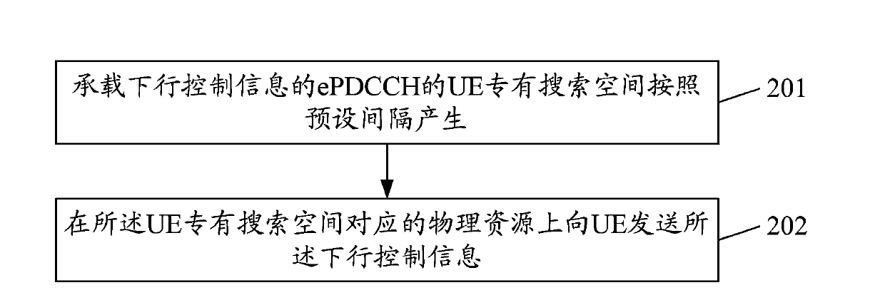
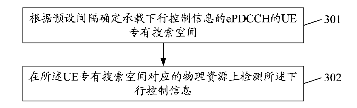
The invention discloses a method for sending and detecting downlink control information, a sending terminal and a receiving terminal. The method comprises the following steps of according to the preset interval, determining a special searching space of a user terminal (UE (user equipment)) of an ePDCCH (enhanced physical downlink control channel) carrying downlink control information, wherein the preset interval is determined according to the number of candidate positions of a component carrier with a corresponding aggregation level in a corresponding resource set, or according to the number of candidate positions of the component carrier with the corresponding aggregation level in the corresponding resource set or the number of dispatched component carriers, or according to the number of candidate positions of the component carrier with the corresponding aggregation level in the corresponding resource set or the number of configured component carriers; detecting the downlink control information in the physical resource corresponding to the special searching space of the UE. The method can solve the detecting problem of the ePDCCH.
Description
technical field [0001] The present invention relates to downlink control information detection technology in the communication field, in particular to a method for sending and detecting downlink control information, a sending end and a receiving end. Background technique [0002] A Physical Downlink Control Channel (PDCCH, Physical Downlink Control Channel) is defined in a Long Term Evolution (LTE, Long Term Evolution) system. The PDCCH is used to carry downlink control information (DCI, Downlink Control Information). The physical resources transmitted by the PDCCH are in units of Control Channel Elements (CCE, Control Channel Element), and the size of a CCE is 9 Resource Element Groups (REG, Resource Element Group ), that is, 36 resource elements (Resource Element), and one PDCCH occupies 1, 2, 4 or 8 CCEs. For the four PDCCHs occupying 1, 2, 4, and 8 CCEs, tree-like aggregation (Aggregation) is adopted, that is, a PDCCH occupying 1 CCE can start from any CCE position, and...
Claims
Application Information
Patent Timeline
Application Date:The date an application was filed.
Publication Date:The date a patent or application was officially published.
First Publication Date:The earliest publication date of a patent with the same application number.
Issue Date:Publication date of the patent grant document.
PCT Entry Date:The Entry date of PCT National Phase.
Estimated Expiry Date:The statutory expiry date of a patent right according to the Patent Law, and it is the longest term of protection that the patent right can achieve without the termination of the patent right due to other reasons(Term extension factor has been taken into account ).
Invalid Date:Actual expiry date is based on effective date or publication date of legal transaction data of invalid patent.

