Assemblable and disassemblable container

a container and disassembly technology, applied in the direction of packaging, clamping mechanism, large containers, etc., can solve the problems of insufficient strength of the damage to the fitting protruding portion formed on the first support wall, etc., to achieve increased strength and rigidity, increase increase in strength and rigidity

Active Publication Date: 2014-08-05
SANKO CO LTD
View PDF11 Cites 7 Cited by
  • Summary
  • Abstract
  • Description
  • Claims
  • Application Information

AI Technical Summary

Benefits of technology

[0010]The container comprises the one bottom member, the first set of two wall members, and the second set of two wall members, and the container is assembled in such a manner that the two wall members of the first set lie opposite each other and that two wall members of the second set lie opposite each other, by fitting the fitting blocks formed on the endwise vertical side plate portion of the wall member of the second set into the fitting space portions formed in the vertically elongate coupling portion of the wall member of the first set, and furthermore, the first set of wall members and the second set of wall members are each coupled to the bottom member by fitting the fitting block members suspended from back surfaces of lower-end horizontal flanges of the wall member of the first set and the wall member of the second set into the respective fitting vertical slots formed in the bottom member, and moreover, the wall member of the second set includes the upper corner reinforcing members each formed at the corresponding corner formed by the upper horizontal flange and an endwise vertical side plate portion of the wall member of the second set. The upper corner reinforcing member includes the inclined coupling rib coupling the vicinity of the end of the upper horizontal flange to the vicinity of the upper end of the endwise vertical side plate portion. The lower end of the inclined coupling rib is positioned close to the endwise vertical side plate portion side of the lower horizontal rib of the horizontal portion included in the fitting block member. As a result, the second set of wall members and thus the container assembled into a box shape can be increased in strength and rigidity. Furthermore, the container can be prevented from undergoing torsional deformation.
[0011]Furthermore, the horizontal rib formed on the upper corner reinforcing member is arranged in a substantially collinear manner with respect to the upper horizontal rib of the horizontal portion formed on the corresponding fitting block member. Thus, the container can be increased in strength and rigidity and be prevented from undergoing torsional deformation. The fitting block members can also be increased in strength and rigidity.
[0012]Moreover, the horizontal ribs or corner horizontal reinforcing ribs formed on the wall member of the second set are each arranged in a substantially collinear manner with respect to the upper horizontal rib of the horizontal portion formed on the corresponding fitting block member. As a result, the second set of wall members and thus the container assembled into a box shape can be increased in strength and rigidity. Furthermore, the container can be prevented from undergoing torsional deformation. The fitting block members can also be increased in strength and rigidity.
[0013]Moreover, the viewing through-slot is formed in the vertical side plate portion of each of the vertically elongate coupling portions of the wall member of the first set so as to overlap the fitting space formed in the vertically elongate coupling portion, and the end of each of the horizontal ribs formed on the wall member of the first set is arranged in abutting contact with the vertically elongate coupling portion positioned close to the corresponding viewing through-slot. As a result, the vertical coupling portion positioned close to the viewing through-slot and thus the first set of wall members can be increased in strength and rigidity.

Problems solved by technology

However, disadvantageously, the fitting protruding portion formed on the first support wall is insufficient in strength and may thus be damaged.
The fitting protruding portion formed on the first support wall may also be damaged while coupled to the second support wall.

Method used


Image

  • Assemblable and disassemblable container
  • Assemblable and disassemblable container
  • Assemblable and disassemblable container

Examples


Embodiment Construction

[0041]An embodiment of the present invention will be described below. However, the present invention is not limited to this embodiment, and any other embodiment is possible unless such an embodiment departs from the spirits of the present invention.

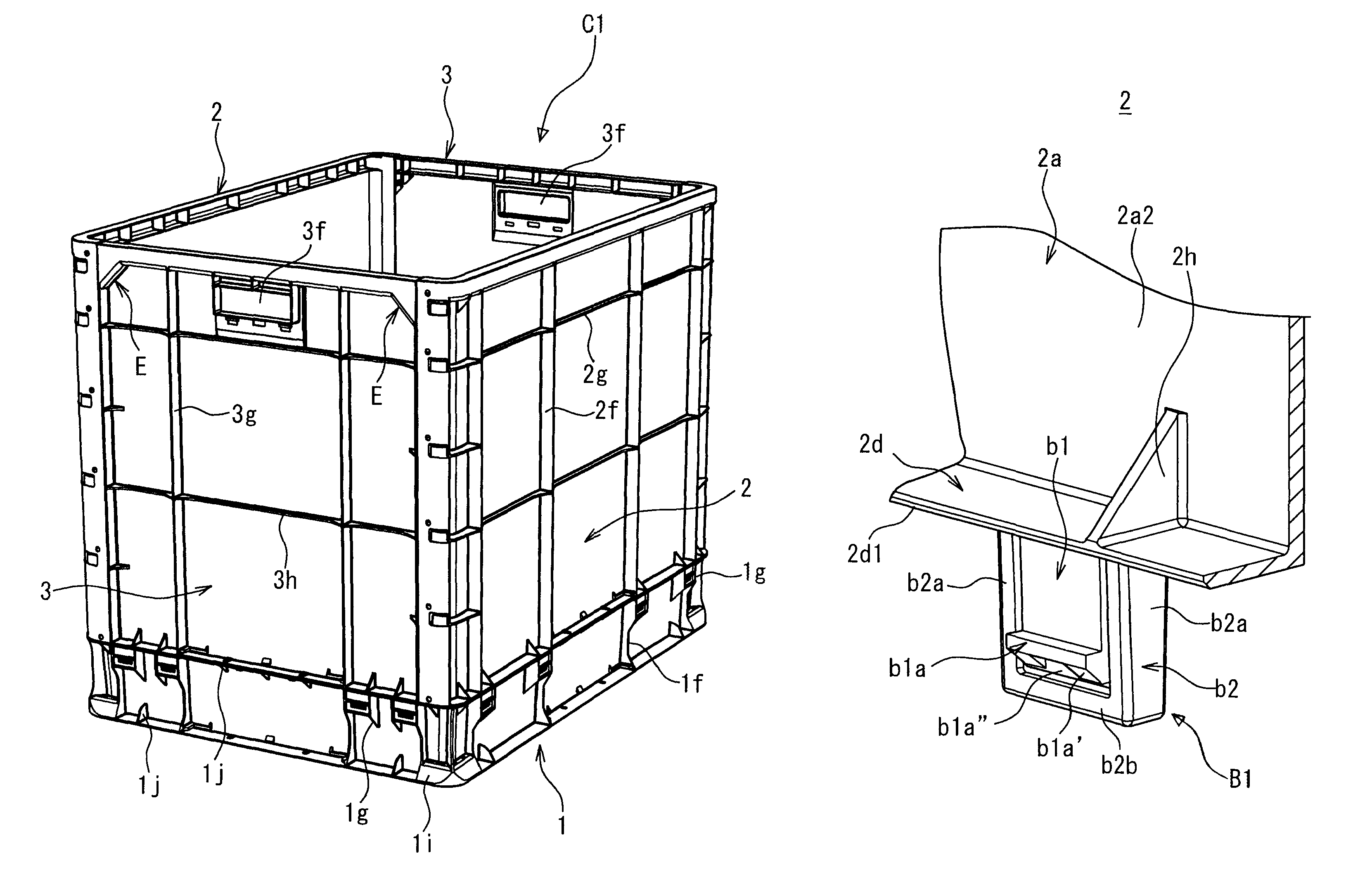
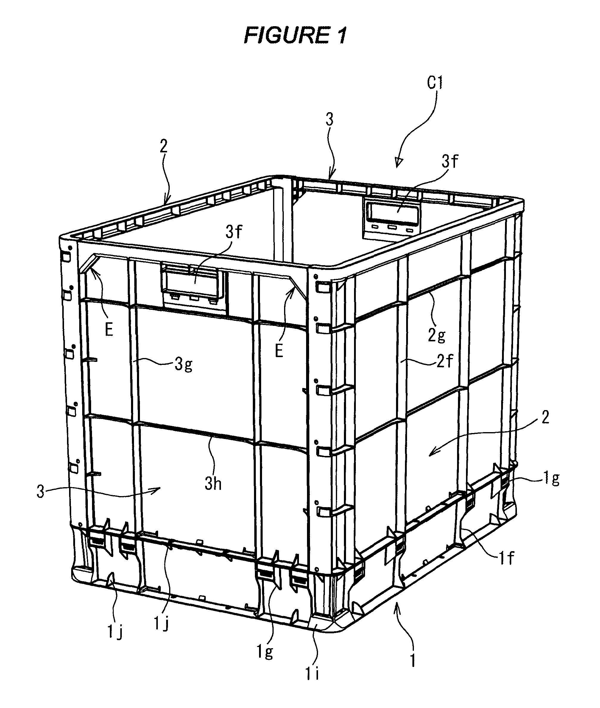
[0042]In FIG. 1, an assemblable and disassemblable container (as mentioned above, hereinafter simply referred to as “a container”) is denoted by C1 and includes a bottom member 1, opposite long wall members 2, and opposite short wall members 3.

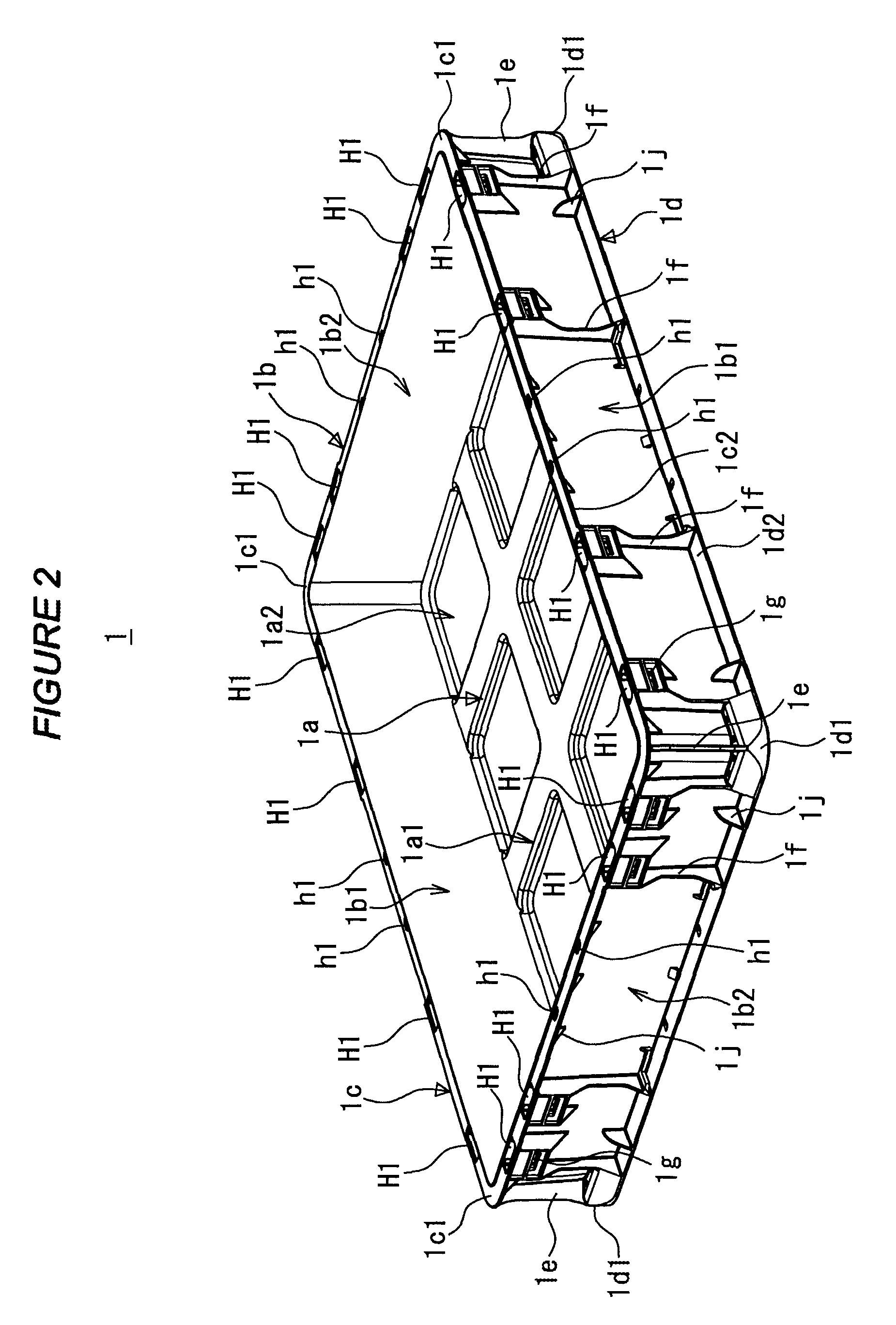
[0043]Now, the bottom member 1 will be described with reference to FIG. 2 and FIG. 3.

[0044]The bottom member 1 includes a bottom plate portion 1a with a substantially rectangular planar shape and a peripheral wall portion 1b erected integrally with the bottom plate portion 1a. The peripheral wall portion 1b includes long side peripheral walls 1b1 erected on opposite long side portions of the bottom plate portion 1a and short side peripheral walls 1b2 erected on opposite short side portions of the bo...


PUM


Abstract

An assemblable and disassemblable container is disclosed wherein a short wall member includes upper corner reinforcing members each formed at a corresponding corner formed by an upper horizontal flange and an endwise vertical side plate portion of the short wall member, and the upper corner reinforcing member includes an inclined coupling rib coupling the vicinity of the end of the upper horizontal flange to the vicinity of the upper end of the endwise vertical side plate portion, and wherein the lower end of the inclined coupling rib is positioned close to an endwise vertical side plate portion side of a lower horizontal rib of a horizontal portion included in a fitting block member. This configuration allows the short wall members and thus the container formed into a box shape to be increased in strength and rigidity, and can be prevented from undergoing torsional deformation.

Description

FIELD OF THE INVENTION[0001]The present invention relates to an assemblable and disassemblable container (hereinafter simply referred to as “a container”) that can be assembled and then disassembled.BACKGROUND OF THE INVENTION[0002]An examined Japanese Utility Model Publication (Jikko-Hei) No. 3-26129 discloses a container configured such that in order to increase the height of a container main body that cannot be disassembled, an orifice frame shaped like a rectangular shell is placed on the container main body.SUMMARY OF THE INVENTION[0003]In the container disclosed in the examined Japanese Utility Model Publication (Jikko-hei) No. 3-26129, the container main body itself cannot be assembled or disassembled.[0004]In the above-described orifice frame, a fitting protruding wall formed on a first support wall is fitted into a fitting recessed portion formed in a second support wall to couple the first and second support walls together. However, disadvantageously, the fitting protrudin...

Claims


Application Information

Patent Timeline
Patent Type & Authority Patents(United States)
IPC IPC(8): B65D6/16B65D6/24B65D6/34B65D90/08
CPCB65D11/1873
Inventor YAMAUCHI, HISATOSHI
Owner SANKO CO LTD
Why Eureka
Try Eureka