
Trocar assembly with pneumatic sealing

a technology of pneumatic sealing and trocar, which is applied in the field of surgical access devices, can solve the problems of affecting the free movement of surgical instruments and/or removal, affecting the safety of surgical instruments,

Active Publication Date: 2014-08-05
SURGIQUEST
View PDF166 Cites 129 Cited by
  • Summary
  • Abstract
  • Description
  • Claims
  • Application Information

AI Technical Summary

Problems solved by technology

However, sealing in this manner is not usually complete, such seals cannot seal between multiple instruments, and such seals also inhibit free movement of the surgical instruments and / or removal of tissue through the trocar.
Such seals are also vulnerable to damage during the surgical procedure.
However, these types of mechanical valves suffer from similar drawbacks.
Most valves, and particularly duckbill-type valves, which include resilient valve members that directly contact surgical instruments, not only interfere with the movement of surgical instruments, but reduce the ability of a surgeon to accurately sense the patient anatomy on which the surgeon is operating.
Moreover, when the endoscope passes through mechanical seals, lenses thereof can be dirtied, typically with smears appearing, resulting in further vision difficulty.

Method used


Image

  • Trocar assembly with pneumatic sealing
  • Trocar assembly with pneumatic sealing
  • Trocar assembly with pneumatic sealing

Examples


Embodiment Construction

[0027]The present invention is now described more fully with reference to the accompanying drawings, in which an illustrated embodiment of the present invention is shown. The present invention is not limited in any way to the illustrated embodiment as the illustrated embodiment described below is merely exemplary of the invention, which can be embodied in various forms, as appreciated by one skilled in the art. Therefore, it is to be understood that any structural and functional details disclosed herein are not to be interpreted as limiting, but merely as a basis for the claims and as a representative for teaching one skilled in the art to variously employ the present invention. Furthermore, the terms and phrases used herein are not intended to be limiting but rather to provide an understandable description of the invention.

[0028]Where a range of values is provided, it is understood that each intervening value, to the tenth of the unit of the lower limit unless the context clearly d...


PUM


Abstract

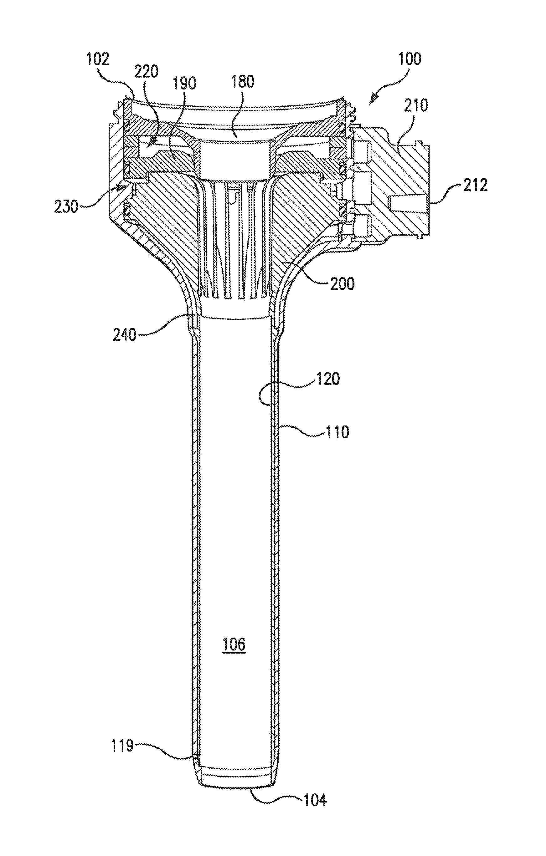
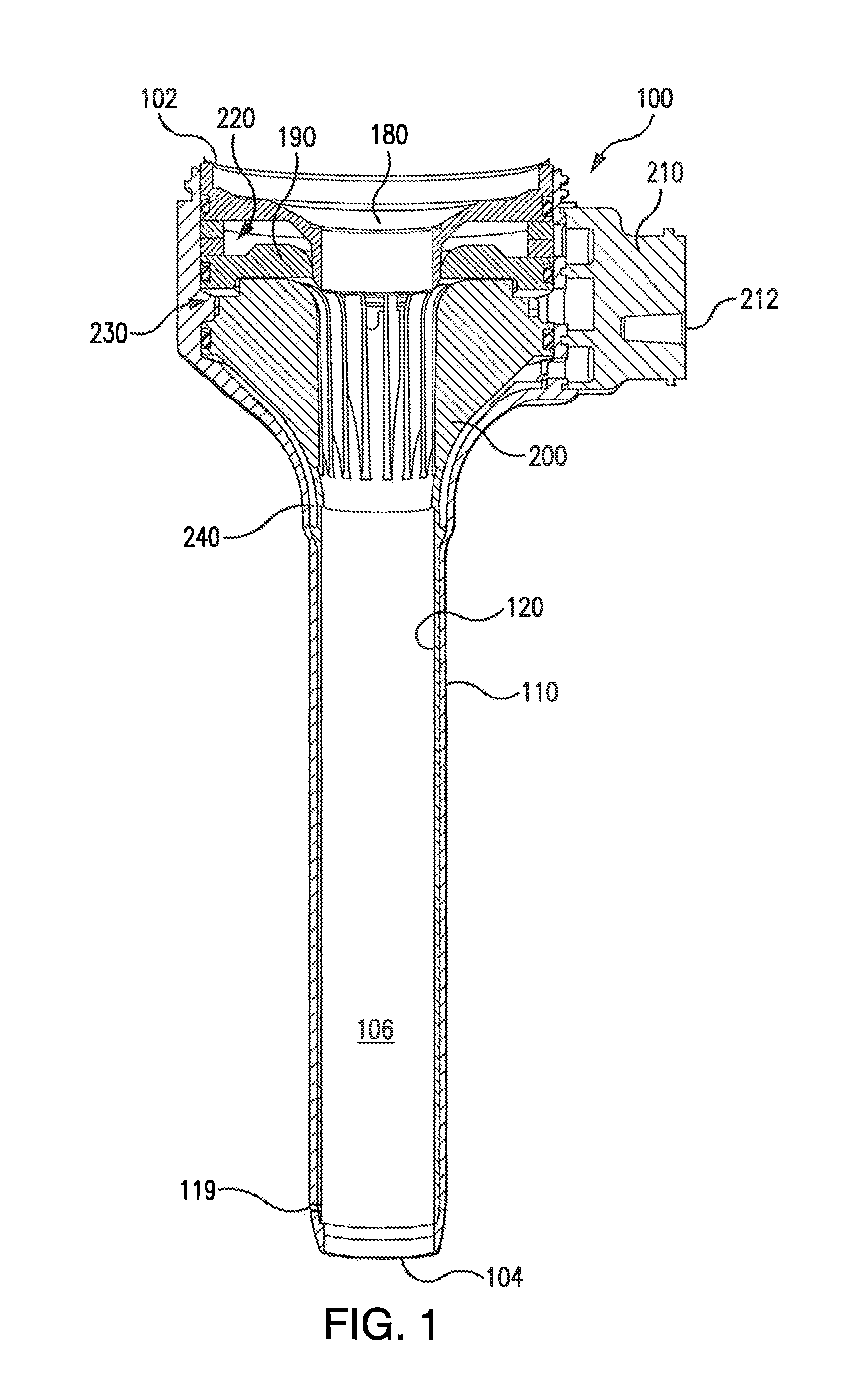
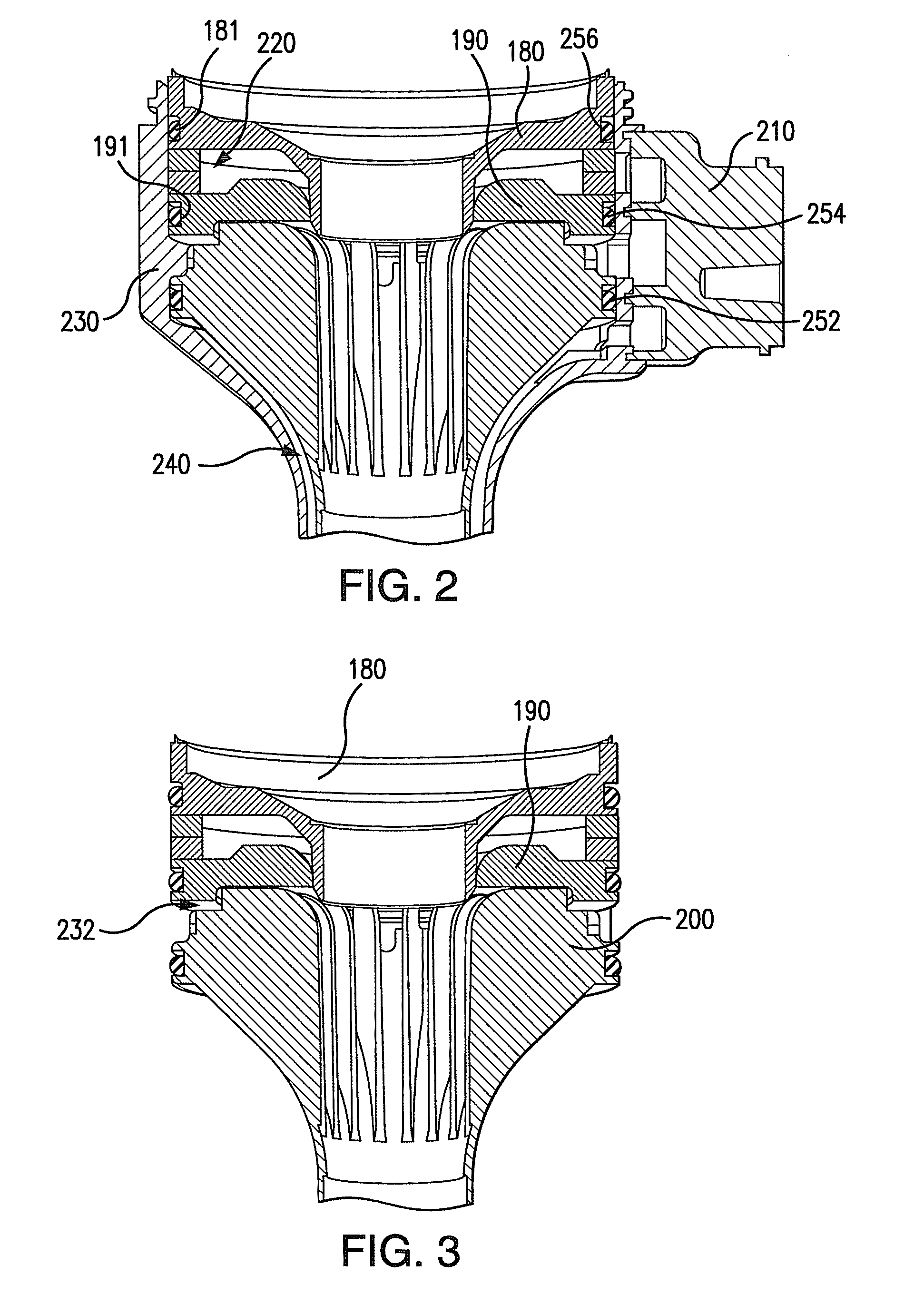
A trocar assembly for creating a pneumatic seal during a minimally-invasive surgical procedure. The trocar assembly including an elongated body having a lumen extending therethrough. The proximal end portion of the body defining a housing. A fluid supply plenum is defined in the housing configured to deliver pressurized insufflation fluid to a nozzle. The nozzle configured for directing pressurized fluid into the lumen and creating a pneumatic seal. A fluid return plenum is defined in the housing configured to collect spent insufflation fluid from as patient's abdominal cavity. The fluid return plenum including a plurality of axially and radially oriented elongate vanes configured to permit spent insufflation fluid to proceed between the vanes and direct spent insufflation fluid back to the fluid return plenum.

Description

CROSS-REFERENCE TO RELATED APPLICATIONS[0001]This application claims priority to U.S. Patent Application Ser. No. 61 / 450,281, filed Mar. 8, 2011, which is incorporated herein by reference in its entirety. This patent application is also related to U.S. Pat. No. 7,854,724, filed Sep. 8, 2006, U.S. patent application Ser. No. 12 / 577,179, filed Oct. 10, 2009, U.S. patent application Ser. No. 12 / 577,189, filed Oct. 11, 2009, U.S. patent application Ser. No. 12 / 587,584, filed Oct. 9, 2009, U.S. Provisional Patent Application Ser. No. 61 / 250,521, filed Oct. 11, 2009, U.S. patent application Ser. No. 11 / 786,832, filed Apr. 13, 2007, U.S. patent application Ser. No. 11 / 544,856, filed Oct. 6, 2006 and U.S. Patent Application Ser. No. 61 / 104,501, filed Oct. 10, 2008. Each of the aforementioned patent applications is incorporated by reference herein in its entirety.FIELD OF THE INVENTION[0002]The present disclosure relates to surgical access devices (or surgical access ports) and is particular...

Claims


Application Information

Patent Timeline
Patent Type & Authority Patents(United States)
IPC IPC(8): A61B17/00A61B17/34
CPCA61B17/3462A61B17/3474A61B2017/00477A61B2217/007A61B2017/3445A61B17/3423
Inventor STEARNS, RALPHTANG, RAYMOND YUE-SINGMASTRI, DOMINICK
Owner SURGIQUEST
Learn More