Tube cutting device with rapid separable handle

a cutting device and separable handle technology, applied in the direction of tube shearing machines, manufacturing tools, metal working apparatuses, etc., can solve the problems of user's hand being likely to be injured, time-consuming and inconvenient, etc., and achieve the effect of quick separable handle, quick, easy and convenient switch

Active Publication Date: 2014-08-12
LEE TAI HUNG
View PDF3 Cites 6 Cited by
  • Summary
  • Abstract
  • Description
  • Claims
  • Application Information

AI Technical Summary

Benefits of technology

[0008]The main objective of the present invention is to provide a tube cutting device with a rapid separable handle. The device has advantages of the handle being separable from or combinable with a tube cutter of the tube cutting device as needed, and quick, easy and convenient switch between different usage modes of the tube cutting device. In particular, the present invention is intended to solve disadvantages and problems that when the traditional tube cutter is used to perform tube cutting at middle of the object tube to be cut, user's hand must constantly change its location back and forth upside and downside of the object tube in order to rotate the traditional tube cutter for tube cutting. It is quite time-consuming and inconvenient, and user's hand is likely to be injured by hitting of the object tube and other issues.

Problems solved by technology

It is quite time-consuming and inconvenient, and user's hand is likely to be injured by hitting of the object tube and other issues.

Method used


Image

  • Tube cutting device with rapid separable handle
  • Tube cutting device with rapid separable handle
  • Tube cutting device with rapid separable handle

Examples


Embodiment Construction

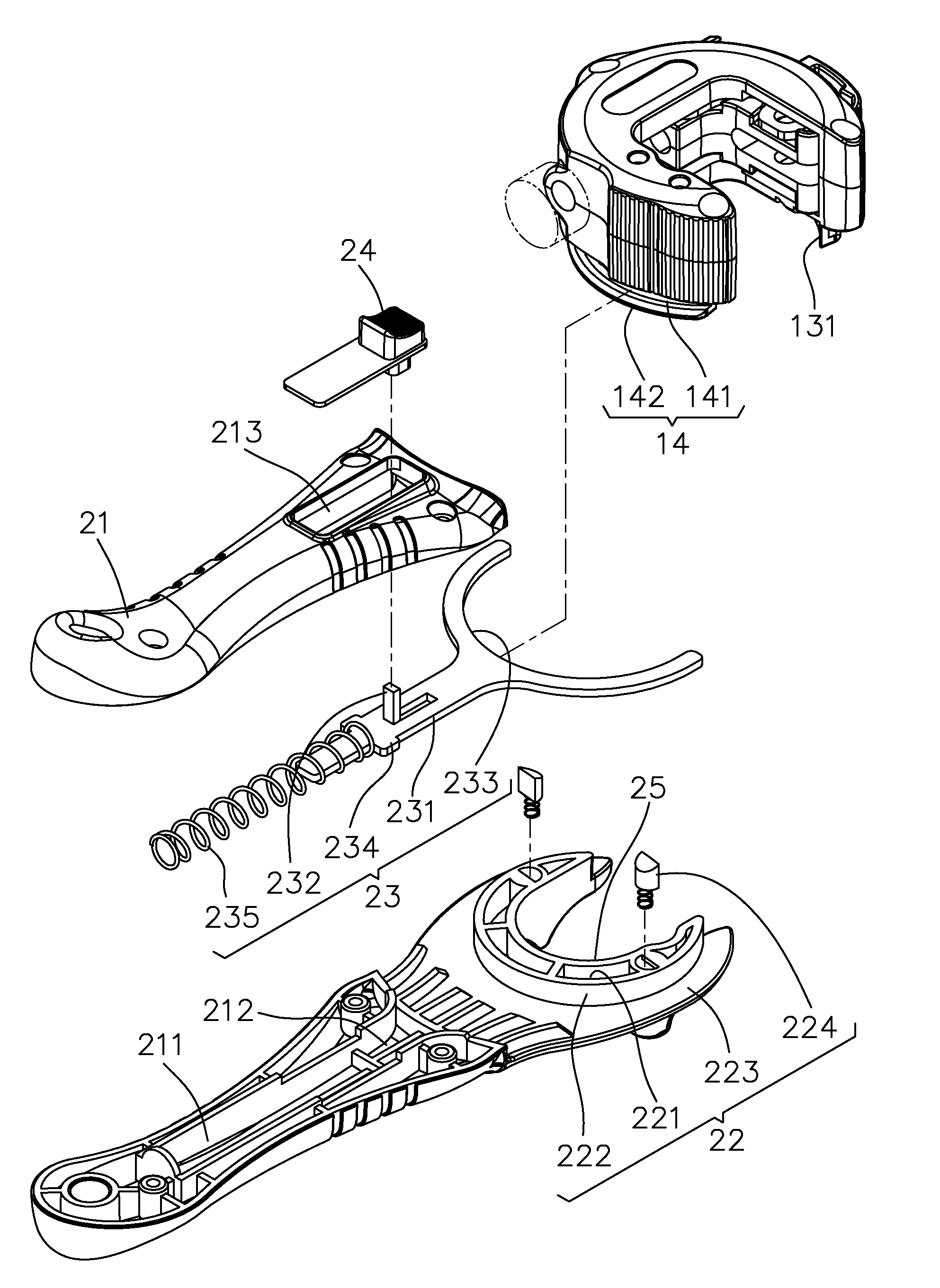
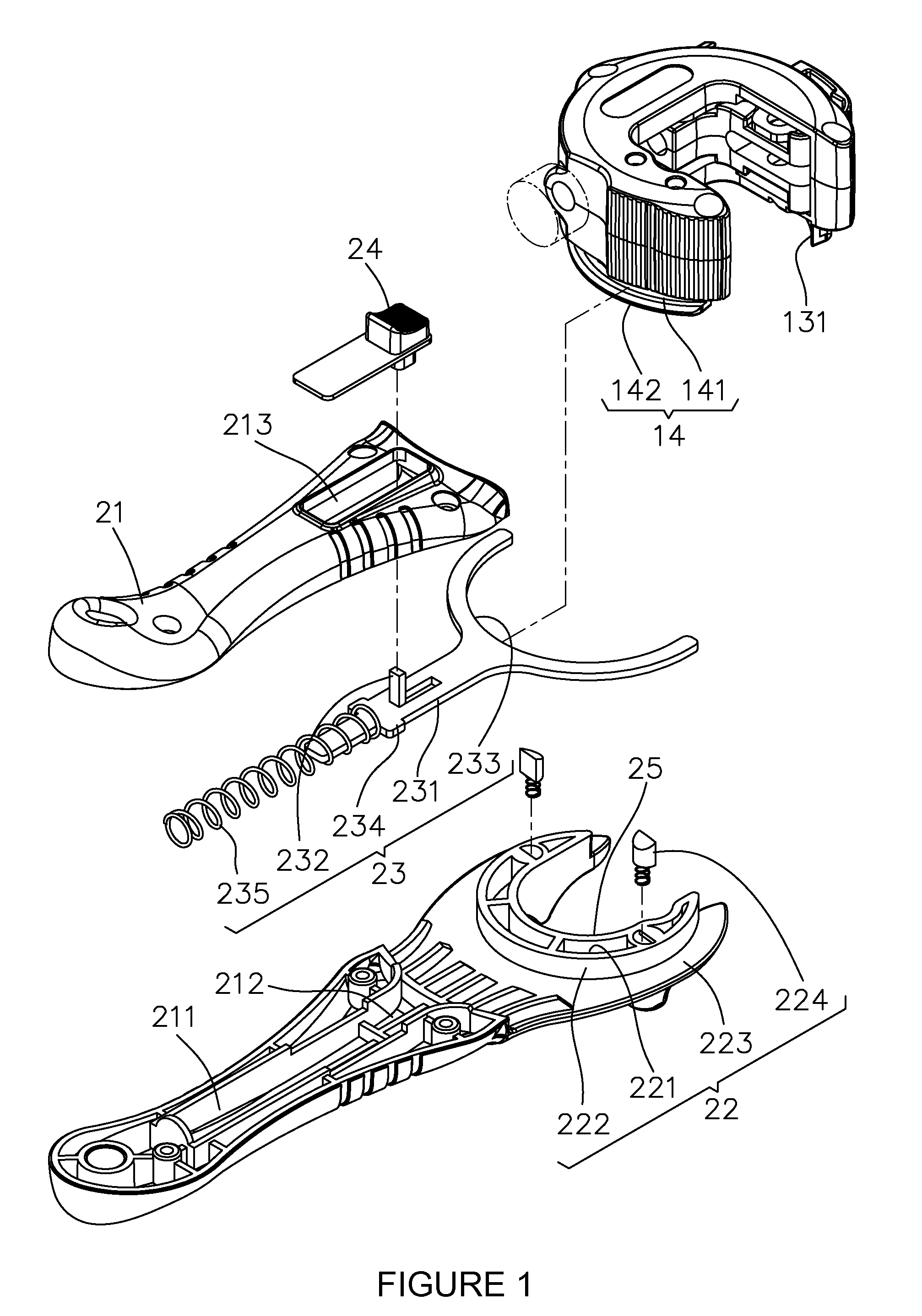
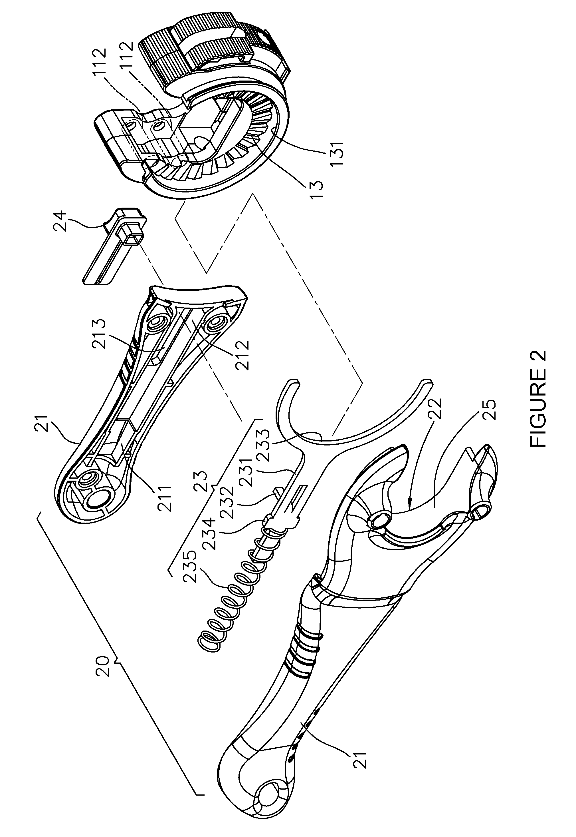
[0019]With reference to FIGS. 1, 2, 3A and 3B, a tube cutting device with a rapid separable handle 20 of the present invention comprises a tube cutter 10 with a C-shaped housing 11, a first recess space 12, a one-way rotation part 13, and a limit part 14.

[0020]The tube cutting device also comprises the handle 20. The handle 20 comprises a grip part 21, a C-shaped guiding seat 22, a separation control part 23, a control button 24 and a second recess space 25. The C-shaped guiding seat 22 is located at the grip part 21 for guiding unidirectional rotation of the C-shaped housing 11 via the one-way rotation part 13. The separation control part 23 is disposed at the grip part 21 and is capable of switching between a combination position P1 and a separation position P2 (Referring to FIG. 4). When located in the combination position P1, the separation control part 23 engages with the limit part 14 so that the tube cutter 10 and the handle 20 are mutually fixed to each other. When located i...


PUM

PropertyMeasurementUnit
timeaaaaaaaaaa
view angleaaaaaaaaaa
resilientaaaaaaaaaa

Abstract

A tube cutting device with a rapid separable handle comprises a tube cutter and a handle. The tube cutter comprises a C-shaped housing, a one-way rotation part, and a limit part. The handle comprises a grip part, a C-shaped guiding seat, a separation control part, and a control button. The C-shaped guiding seat is for unidirectional rotation of the C-shaped housing via the one-way rotation part. In a combination position, it engages with the limit part so that the tube cutter and the handle are mutually fixed. In a separation position, it is separated from the limit part so that the tube cutter and the handle are separable from each other for independently perform tube cutting.

Description

BACKGROUND OF THE INVENTION[0001]1. Field of the Invention[0002]The present invention relates to a tube cutting device with a rapid separable handle, particularly refers to a tube cutting device with a rapid separable handle having advantages of the handle being separable from or combinable with a tube cutter of the tube cutting device as needed, and quick, easy and convenient switch between different usage modes of the tube cutting device, and so on.[0003]2. The Related Arts[0004]With reference to FIGS. 6 and 7, traditional tube cutters 80 mainly comprise a main body 81 being a C-shaped structure, a rotary cutter 82 located at the main body 81, a plurality of rollers 83 located at the main body 81, and at least one lever arm 84 for moving the main body 81.[0005]In this way, the tube cutter 80 is moved through the lever arm 84 to perform tube cutting operations on tubes (Public known as prior art, herein not shown in Figures) by using the rotary cutter 82 in cooperation with the plu...

Claims


Application Information

Patent Timeline
Patent Type & Authority Patents(United States)
IPC IPC(8): B23D21/06
CPCB23D21/06B26D3/169
Inventor LEE, TAI-HUNG
Owner LEE TAI HUNG
Why Eureka
Try Eureka