Arrangement and method for cooling of coolant in a cooling system in a vehicle

a cooling system and cooling system technology, applied in the direction of instruments, lighting and heating apparatus, process and machine control, etc., can solve the problems of shortening the service life of the radiator, large thermal stress on the material of the radiator, and expensive procuremen

Inactive Publication Date: 2014-11-06
SCANIA CV AB
View PDF3 Cites 6 Cited by
  • Summary
  • Abstract
  • Description
  • Claims
  • Application Information

AI Technical Summary

Benefits of technology

[0004]The object of the present invention is to propose a cooling system in a vehicle which reduces the risk of a thermostat opening

Problems solved by technology

The radiator which cools the coolant in the cooling system of heavy vehicles will have a large cooling capacity and therefore be quite expensive to procure.
Conventional thermostats switch abruptly between the closed state and the open state, subjecting the radiator and connecting units in the cooling system to very rapid temper

Method used


Image

  • Arrangement and method for cooling of coolant in a cooling system in a vehicle
  • Arrangement and method for cooling of coolant in a cooling system in a vehicle

Examples


Embodiment Construction

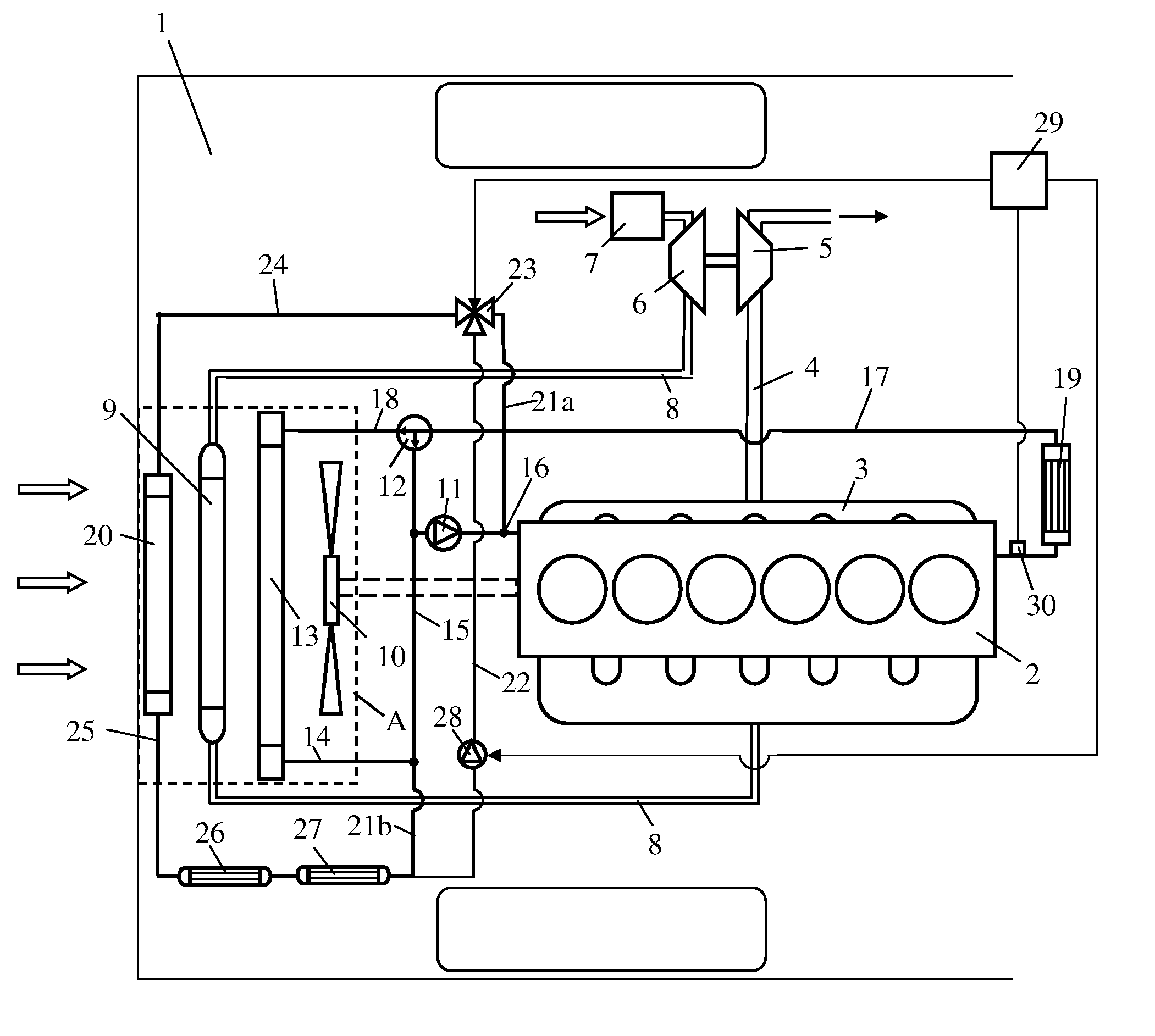
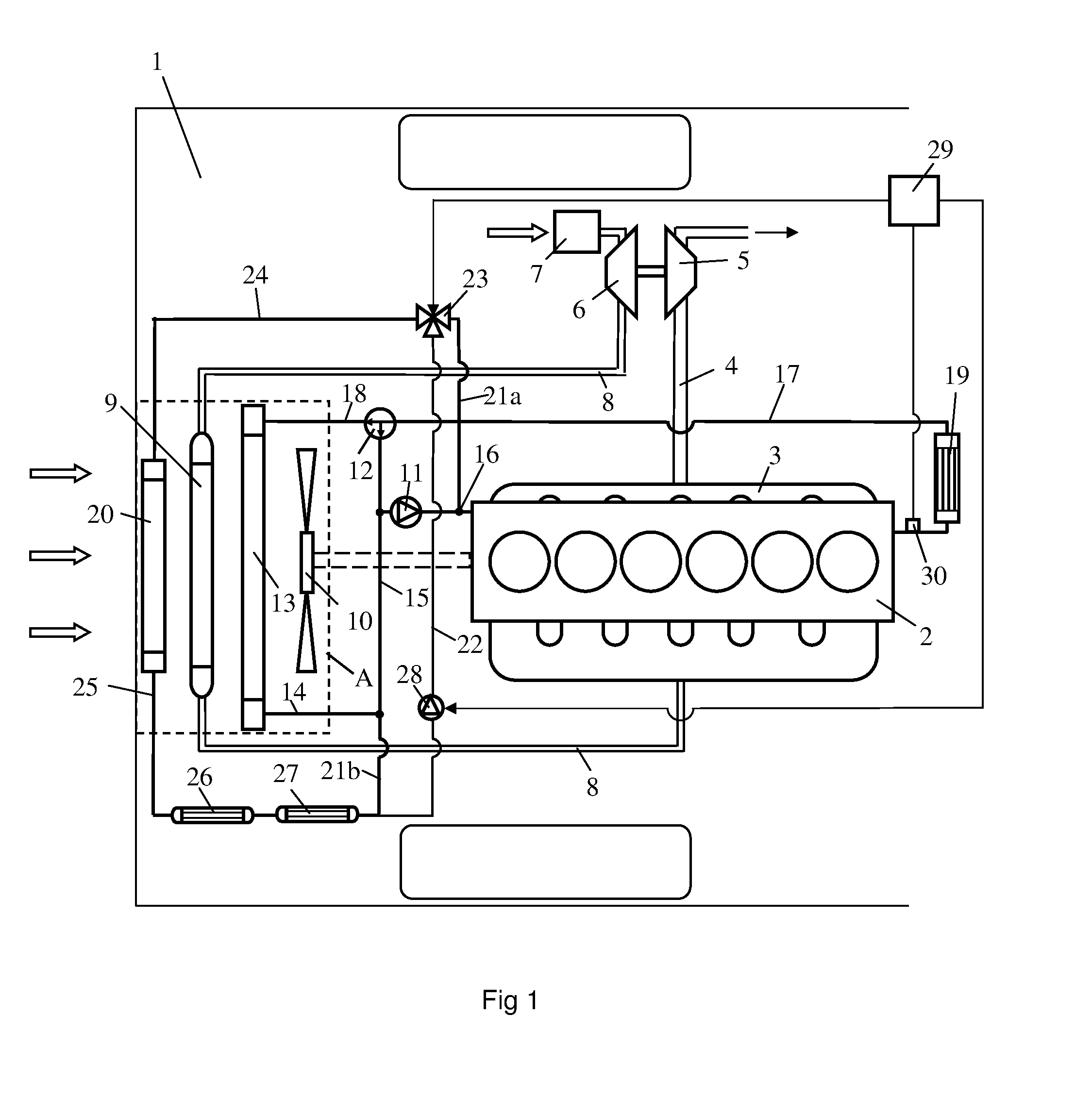
[0016]FIG. 1 depicts a vehicle 1 powered by combustion engine 2. The vehicle may be a heavy vehicle and the engine a diesel engine. The exhaust gases from the engine's cylinders are led to an exhaust line 4 via an exhaust manifold 3. The exhaust gases in the exhaust line 4, which will be at a positive pressure, are led to a turbine 5 of a turbo unit, thus providing the turbine with driving force which is transferred via a connection to a compressor 6. The compressor compresses the air led into an inlet line 8 via an air filter 7. A charge air cooler 9 is situated in the inlet line 8 in a region A in a front section of the vehicle. The purpose of the charge air cooler is to cool the compressed air before it is led to the engine. The compressed air is cooled in the charge air cooler by air forced through the charge air cooler by a radiator fan 10 and the draught caused by the vehicle's forward movement. The radiator fan is driven by the engine by means of a suitable connection.

[0017]T...


PUM


Abstract

An arrangement and a method for cooling coolant in a cooling system in a vehicle: The cooling system includes a first cooling circuit, a first coolant pump (11) to circulate coolant through the first cooling circuit, a first radiator (13) to cool the coolant, and a thermostat (12) which opens to direct coolant to the first radiator (13) when the coolant is above the thermostat's regulating temperature (t2); and a second cooling circuit includes a second radiator (20) to cool coolant. A flow device (23, 29) selectively transfers a portion of coolant from the first cooling circuit to the second cooling circuit, so that this portion of the coolant is cooled in the second radiator (20) when the coolant in the first cooling circuit is within a temperature range defined by a lowest temperature (t1) at which the coolant initially needs cooling and a highest temperature which is equal to the thermostat's regulating temperature (t2).

Description

BACKGROUND TO THE INVENTION AND PRIOR ART[0001]The present invention relates to an arrangement and a method for cooling of coolant in a cooling system in a vehicle according to the preambles of claims 1 and 11.[0002]The coolant in a cooling system for cooling of a combustion engine in a vehicle needs to be at an operating temperature which is usually within the range 80-90° C. The cooling system usually comprises a thermostat which regulates the coolant's temperature in the cooling system. In operating situations where the thermostat finds that the coolant is below the desired operating temperature, it will be in a closed state whereby the coolant is led to the engine without cooling. Operating situations where the thermostat finds that the coolant is above the desired operating temperature will put the thermostat into an operating state in which it directs the coolant to a radiator for cooling before it is led back to the engine. The radiator is usually situated in the vehicle's fr...

Claims


Application Information

Patent Timeline
IPC IPC(8): F01P7/16F28F27/02
CPCF01P7/16F01P2007/146F28F27/02F01P7/165F01P2003/182F01P2060/04F01P2060/14F01P2025/32F01P2060/06
Inventor KARDOS, ZOLTAN
Owner SCANIA CV AB
Why Eureka
Try Eureka