Hydraulic circuit for construction machinery

A construction machinery and hydraulic circuit technology, applied in the front-end application field, can solve the problems of reducing the replacement time and labor of working tools, and achieve the effect of improving workability, reducing time, and easy operation

Inactive Publication Date: 2010-06-09
NIHON KENKI CO LTD
View PDF3 Cites 6 Cited by
  • Summary
  • Abstract
  • Description
  • Claims
  • Application Information

AI Technical Summary

Problems solved by technology

[0011] However, as shown in Patent Document 1, the structure of fixing the working tool link to the front end arm when using a pendant working tool cannot always connect the working tool link to the adapter as described in Patent Documents 2 and 3. in the case of
Therefore, there is a problem that it is not possible to reduce work tool replacement time and labor.

Method used


Image

  • Hydraulic circuit for construction machinery
  • Hydraulic circuit for construction machinery
  • Hydraulic circuit for construction machinery

Examples


Embodiment Construction

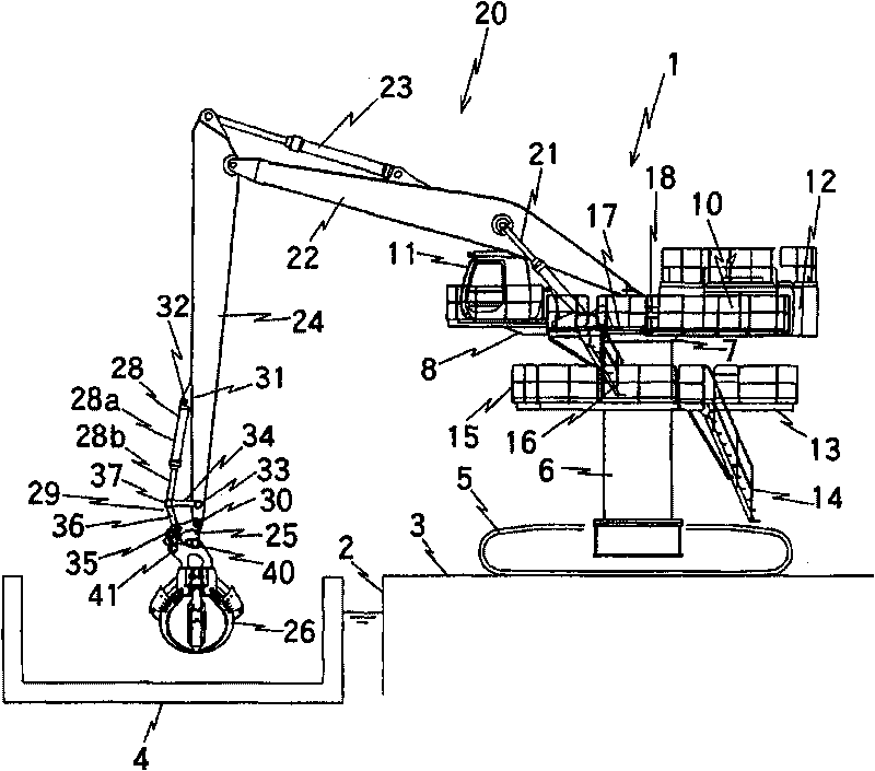
[0033] figure 1 It is a side view showing an example of the construction machine of the present invention. Reference numeral 1 denotes a construction machine that performs loading and unloading work on the ground 3 near the embankment 2 , and is a machine that loads and unloads cargo loaded on a ship 4 . Reference numeral 5 represents a self-propelled undercarriage. In this example, the case where the undercarriage 5 is a crawler-type undercarriage is shown. The condition of the vehicle.

[0034] A tower 6 is provided on the running body frame of the undercarriage 5 , and an upper revolving body 8 is provided on the top of the tower 6 via a revolving device 7 . A hydraulic power unit 10 , a cab 11 , a counterweight 12 and the like are mounted on the upper revolving structure 8 . In the midway of the tower 6 and under the lower surface of the upper revolving body 8 , a platform 13 for maintenance and inspection, such as a hydraulic power unit 10 mounted on the upper revolvin...


PUM


Abstract

The invention provides a hydraulic circuit for construction machineries, in which an adaptor rotated by the hydraulic cylinder is mounted on the construction machinery on the front end arm through a connection rod mechanism, and a suspending type operation tool and a rotation type operation tool are replacable installed on the adaptor. Variable overflow valves are provided, which are connected with a cylinder bottom chamber (28c) of the hydraulic cylinder (28), and each pipelines (75, 76) between the control valves (66) of the piston rod chamber (28d) and the hydraulic cylinder (28). An electromagnetic valve (84) and a switch (86) is provided, wherein the electromagnetic valve can switch the configured pressure of each of the variable overflow valves (82, 83) disposed in parallel with each other and equipped with check valves (93, 94) between a high side overflow pressure and a low side overflow pressure. The switch (86) is shut during the installation of the rotation type operation tool so that the variable overflow valve (82, 83) is configured at the high side overflow pressure. And the switch (86) is opened during the installation of the suspending type operation tool so that the variable overflow valve (82, 83) is configured at the high side over-flow pressure.

Description

technical field [0001] The present invention relates to a hydraulic circuit of a construction machine in which a pendant working tool and a rotary working tool such as a lifting electromagnet, A grab bucket, a tine bucket, and the like can be used hanging down, and the rotary working tool, like a backhoe bucket, needs to be rotated during work. Background technique [0002] In construction machinery, a backhoe bucket (hereinafter, a work tool that needs to be rotated during work like a backhoe bucket is called a rotating work tool.) is mounted on a work arm with a multi-joint structure. In the case of the front end of the working arm, a hydraulic cylinder is attached to the front end arm of the working arm, and the piston rod of the hydraulic cylinder is connected to the backhoe bucket via a link mechanism for increasing the turning angle of the working tool. The link mechanism is composed of a link (hereinafter referred to as an arm link) pivotally connected to the front e...

Claims


Application Information

Patent Timeline
Patent Type & Authority Applications(China)
IPC IPC(8): E02F9/22E02F3/42B66C13/12B66C13/20
CPCB66C13/066B66C3/04E02F9/22F15B11/032
Inventor 浅野政男
Owner NIHON KENKI CO LTD
Why Eureka
Try Eureka