Backplate and backlight module comprising the same

a backlight module and backlight technology, applied in the field of displays technologies, can solve the problems of low light coupling efficiency and discharging aluminum extruded pieces, and achieve the effect of low cost and high light coupling efficiency

Active Publication Date: 2014-08-12
TCL CHINA STAR OPTOELECTRONICS TECH CO LTD
View PDF9 Cites 0 Cited by
  • Summary
  • Abstract
  • Description
  • Claims
  • Application Information

AI Technical Summary

Benefits of technology

[0006]An objective of the present disclosure is to provide a backplate and a backlight module, which have a low cost but a high light coupling efficiency.
[0017]Preferably, the upper surface of the at least one bridging structure is formed with micro-structures or with groove structures recessed inwards to better fix the at least one light source and the light guide plate.
[0024]Preferably, the upper surface of the at least one bridging structure is formed with micro-structures or with groove structures recessed inwards to better fix the at least one light source and the light guide plate.
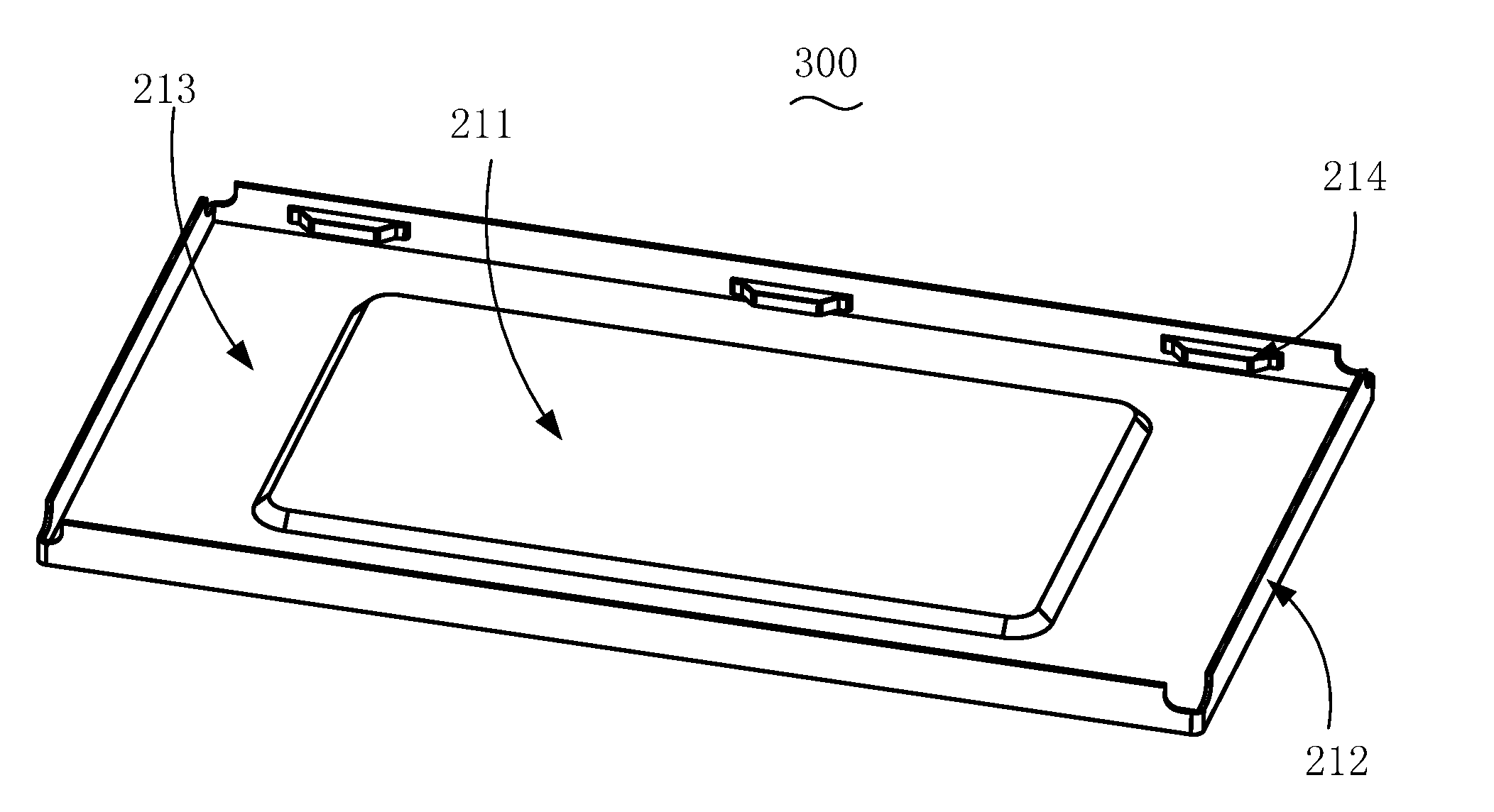
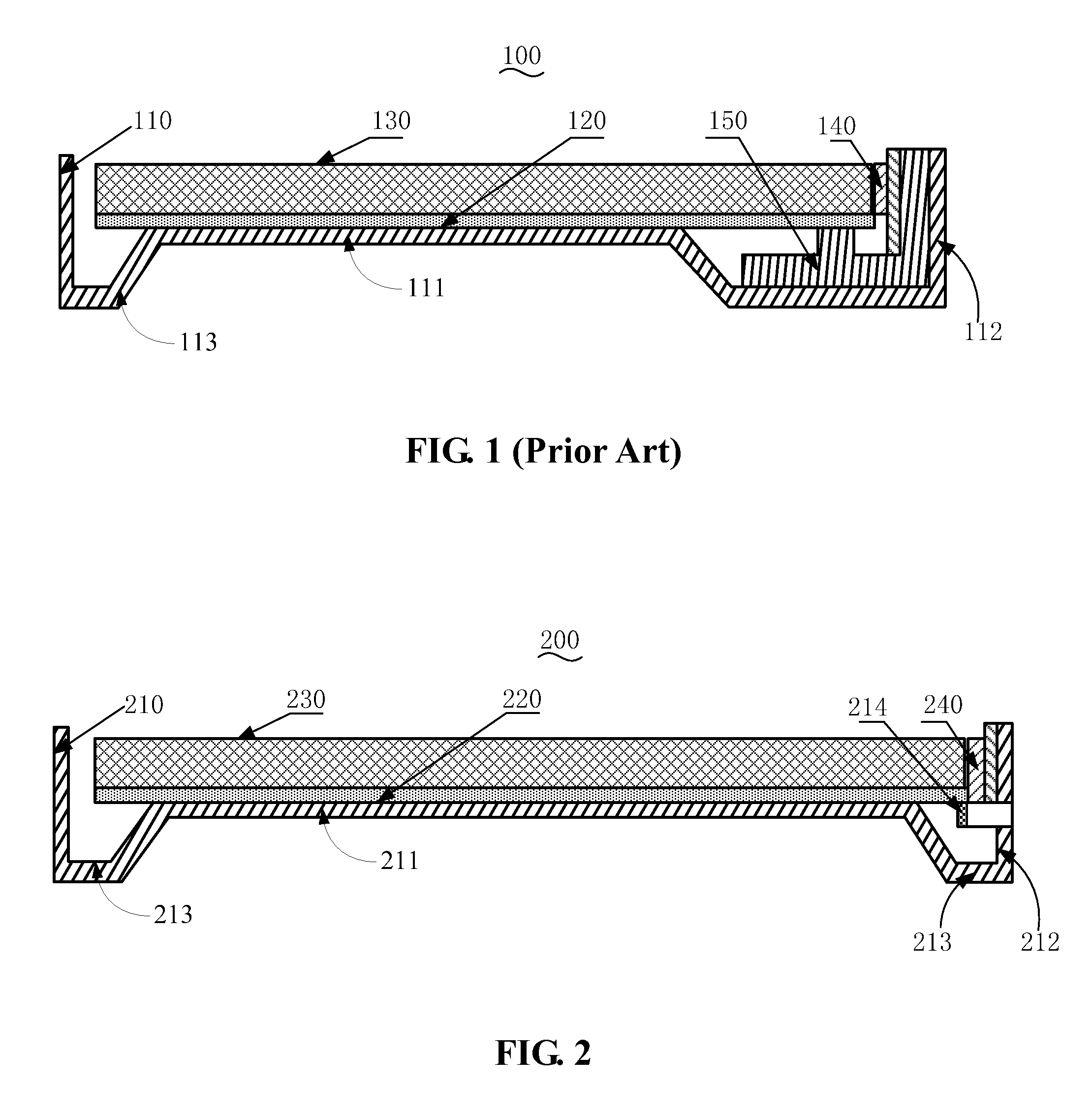
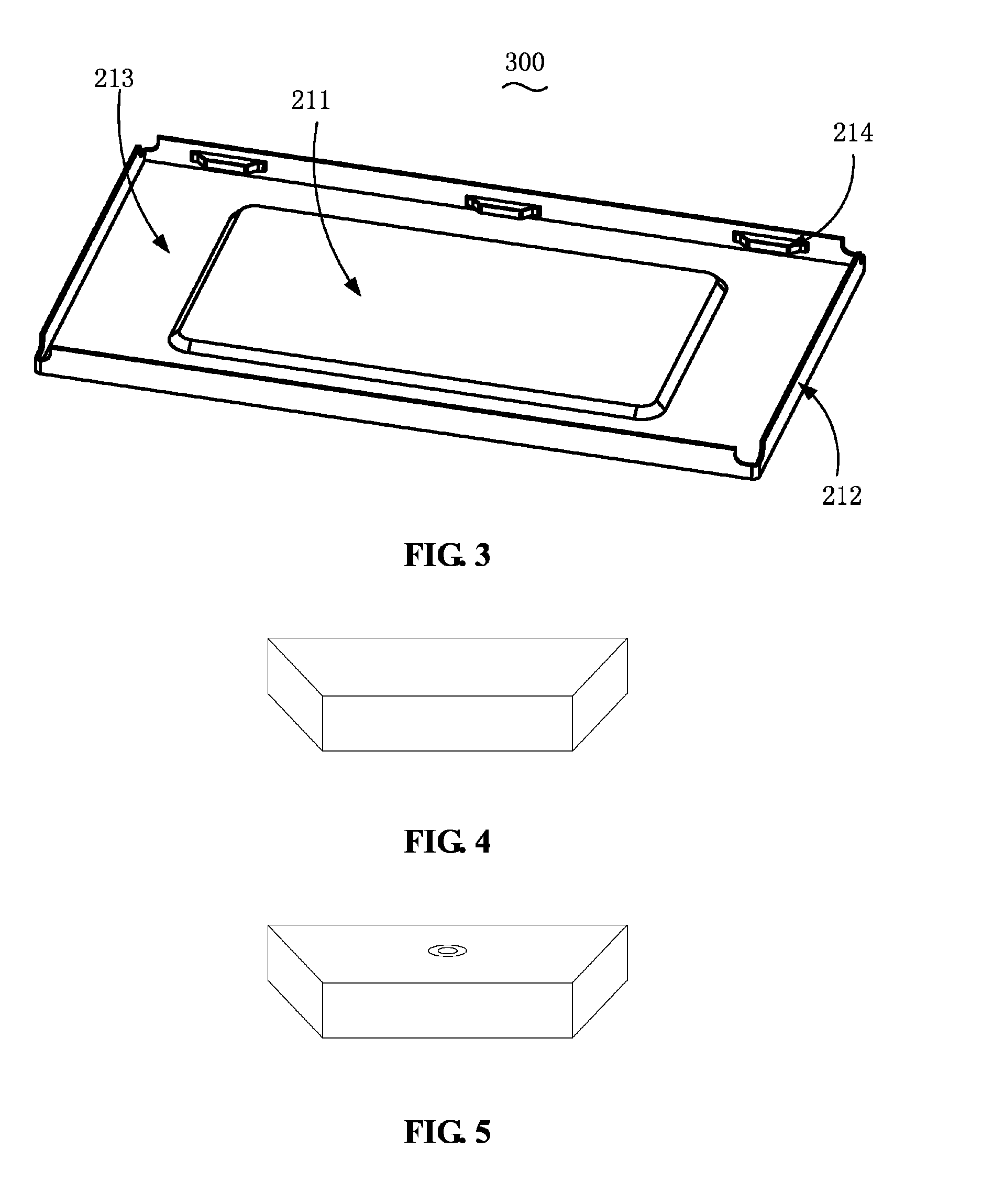
[0027]According to the backplate and the backlight module of the present disclosure, at least one bridging structure for supporting the light source is disposed on the side plate(s) of the backplate, so use of the heat dissipating aluminum extruded piece can be eliminated to reduce the cost; and furthermore, the at least one bridging structure can be used to accurately fix the positions of the light source and the light guide plate relative to each other, so the light coupling efficiency is relatively high.

Problems solved by technology

However, the heat dissipating aluminum extruded piece 150 is relatively costly, and is unable to fix positions of the light source 140 and the light guide plate 130 relative to each other accurately, which leads to a low light coupling efficiency.

Method used


Image

  • Backplate and backlight module comprising the same
  • Backplate and backlight module comprising the same
  • Backplate and backlight module comprising the same

Examples


Embodiment Construction

[0038]Various embodiments of the disclosure are now described in detail. Referring to the drawings, like numbers indicate like parts throughout the views. As used in the description herein and throughout the claims that follow, the meaning of “a,”“an,” and “the” includes plural reference unless the context clearly dictates otherwise. Also, as used in the description herein and throughout the claims that follow, the meaning of “in” includes “in” and “on” unless the context clearly dictates otherwise.

[0039]In order to further describe the technical solutions adopted to achieve the objectives of the present disclosure and the efficacies thereof, implementations, methods, steps, structures, features and efficacies of the color flat display panel and the corresponding color flat display device according to the present disclosure will be detailed hereinbelow with reference to the attached drawings and preferred embodiments thereof. The aforesaid and other technical disclosures, features a...


PUM


Abstract

A backlight module comprises a light guide plate, at least one light source and a backplate. The backplate comprises a baseplate, four side plates and at least one bridging structure. The backplate is used for supporting the light guide plate, and the side plates are disposed perpendicular to the baseplate respectively to form a receiving space for receiving the light guide plate. The at least one bridging structure extends inwards from an inner surface of the side plates by a certain distance to support and locate the at least one light source and the light guide plate. According to the present disclosure, because at least one bridging structure for supporting the light source is disposed on the side plate of the backplate, use of the heat dissipating aluminum extruded piece can be eliminated to reduce the cost; and furthermore, the at least one bridging structure can be used to accurately fix the positions of the light source and the light guide plate relative to each other, so the light coupling efficiency is relatively high.

Description

FIELD OF THE INVENTION[0001]The present disclosure generally relates to the field of displaying technologies, and more particularly, to a backplate for use in a liquid crystal display (LCD) device and a backlight module comprising the backplate.BACKGROUND OF THE INVENTION[0002]Owing to their advantages such as lightweight, thin-profile, energy-saving, and no radiation, flat panel display devices such as liquid crystal display (LCD) devices have gradually replaced the conventional cathode ray tube (CRT) display devices as the mainstream display products. Currently, the LCD devices have found wide applications in various electronic apparatuses including digital TV sets, computers, personal digital assistants (PDAs), mobile phones and digital cameras.[0003]Because an LCD panel does not emit light by itself, generally a backlight module must be disposed beneath the LCD panel to provide an area light source necessary for the LCD panel so that adequate brightness and an adequate contrast ...

Claims


Application Information

Patent Timeline
Patent Type & Authority Patents(United States)
IPC IPC(8): F21V7/04
CPCG02B6/0088G02B6/0085G02B6/0091
Inventor ZHOU, GE-GE
Owner TCL CHINA STAR OPTOELECTRONICS TECH CO LTD
Why Eureka
Try Eureka