Golf practice device

a golf practice and golf technology, applied in the field of improved golf practice devices, can solve the problems of unsatisfactory, player may not have the point of impact under exact control, and rotate around the axis for considerable tim

Active Publication Date: 2014-08-12
TSSGOLF D O O
View PDF13 Cites 6 Cited by
  • Summary
  • Abstract
  • Description
  • Claims
  • Application Information

AI Technical Summary

Problems solved by technology

The problem is that even with a golf swing that looks just perfect, a player may not have the point of impact under exact control.
Training devices have been built to provide a means for practicing all the steps at once, however they were not satisfactory, except for settings that require a lot of space and costly high-tech technology.
The disadvantage of this device is that when the golf player hits the ball, it rotates around its axis for considerable time and has to be stopped by the golfer manually in order to bring it into initial position.
This takes time and it distracts golfer's concentration.
Another disadvantage is that it uses a lightweight plastic ball which does not give the player an authentic feel of a re...

Method used


Image

  • Golf practice device
  • Golf practice device
  • Golf practice device

Examples


first embodiment

b>5B

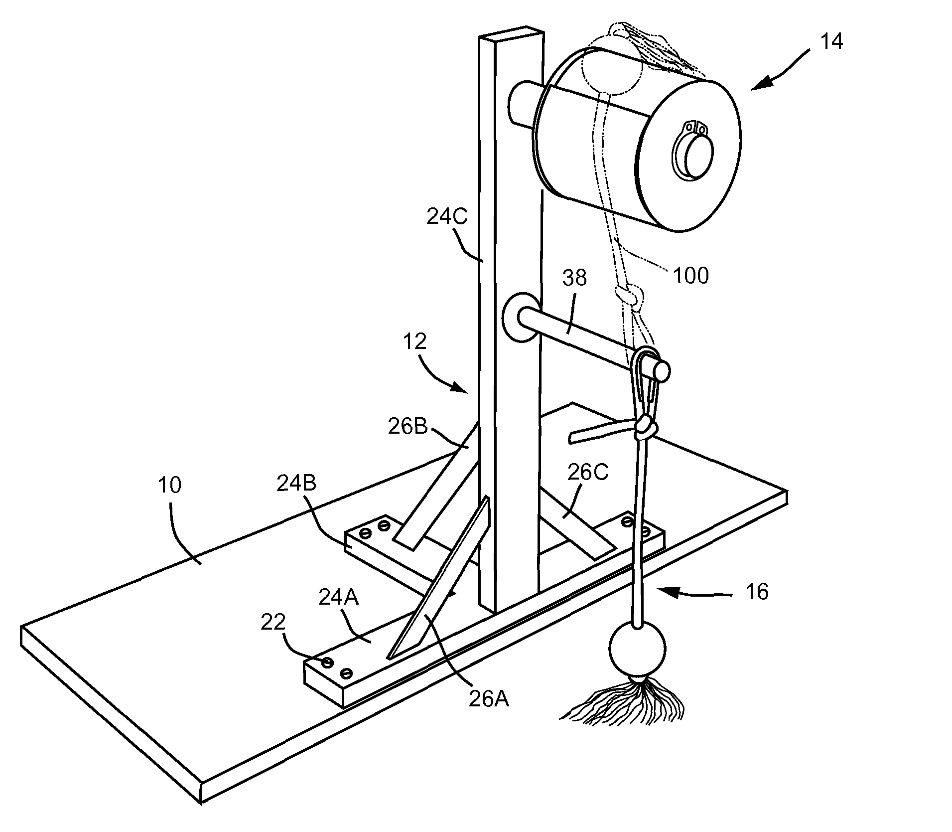
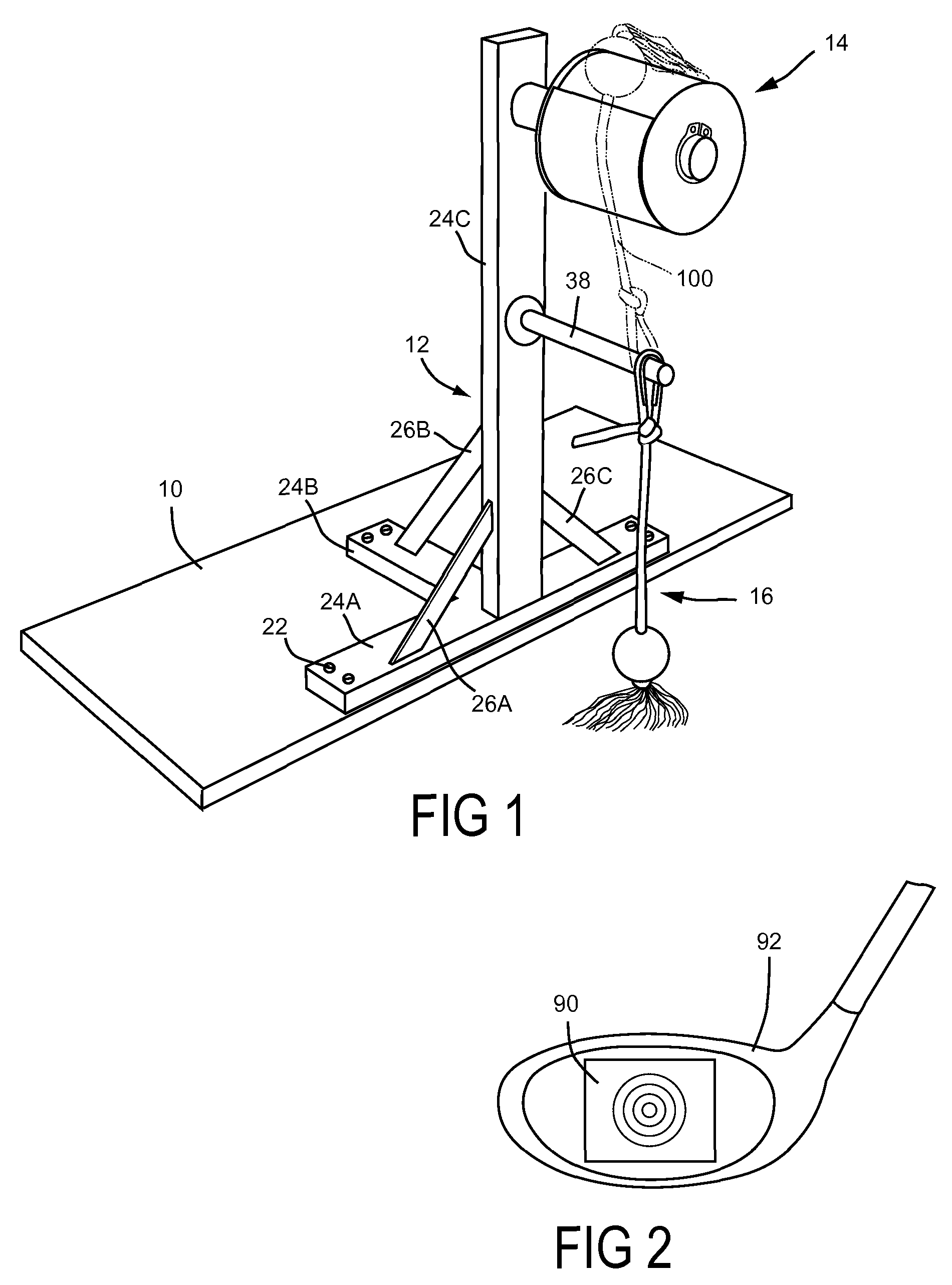
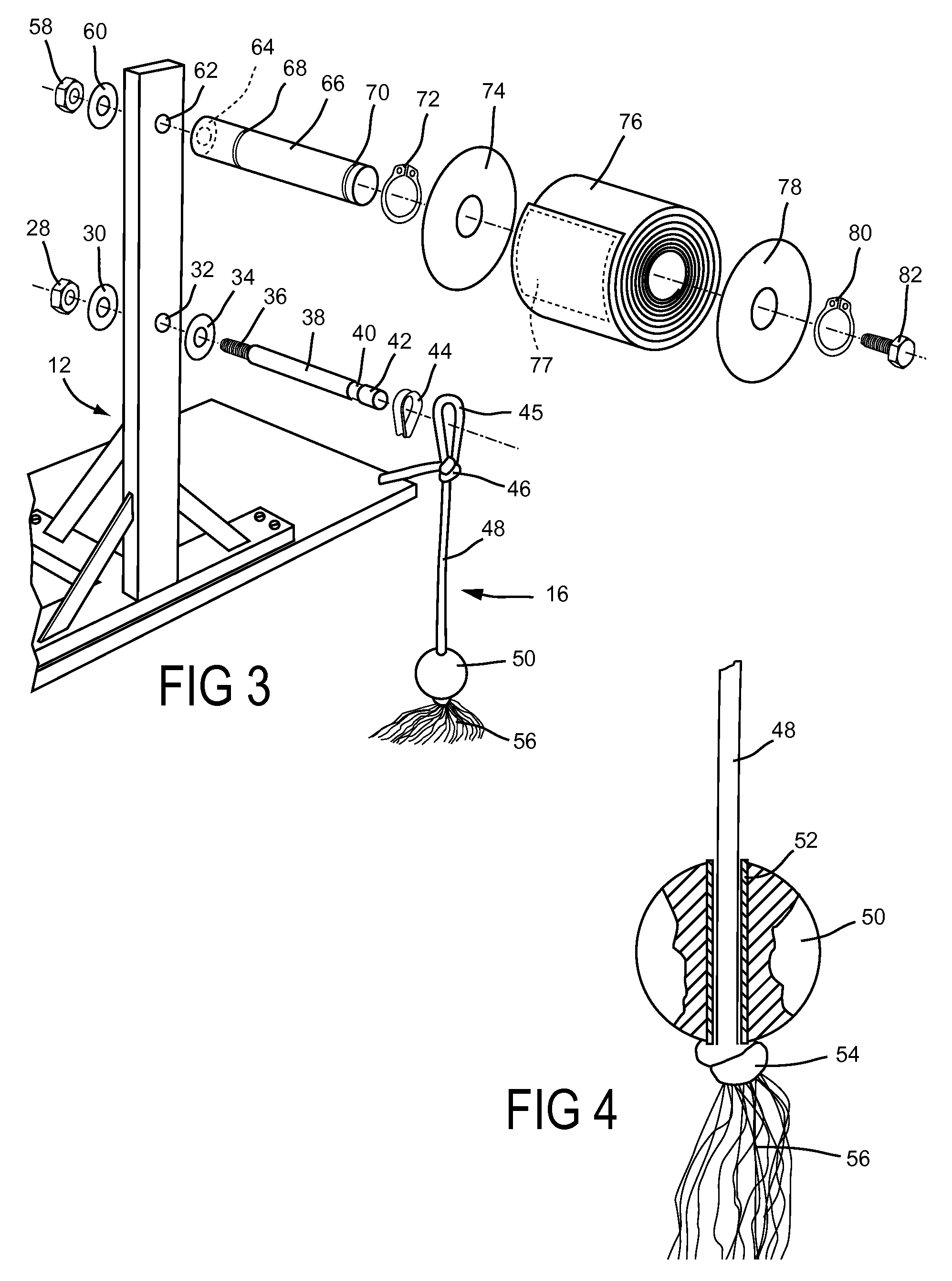
[0071]FIG. 1 shows a perspective view of one version of my device. It comprises a frame, or an upright support 12 that is mounted to a base 10. A shaft 38 is attached to the upright support 12 in a substantial horizontal orientation. A ball body 16 is rotatably mounted to the end portion of the shaft 38. A stopping member 14 is attached in substantial horizontal orientation to the upright support 12 in position above the shaft 38.

[0072]The base 10 is preferably made of wood and is configured to be removably affixed to a surface such that it does not move relative to the player upon the ball body being struck with a golf club 92. Any relatively immovable surface may be used, such as for example, the ground, a floor of a building or the deck of a ship. It may be removably affixed to the surface using any means common or convenient for such purpose, for example using double sided tape, glue, nails, clamps, or weights.

[0073]The upright support 12 is preferably welded together from r...

second embodiment

[0084]One difference in relation to the first embodiment is that here the stopping member 14 (FIG. 1) is simplified. As shown in FIG. 6, a tube 166 is mounted to the upright support 12 in the same way as the tube 66 in the first embodiment. The tube 166 has two circular grooves 168, 170, and two seeger rings 172, 180 are placed into circular grooves 168, 170 respectively to lock a cylinder with a hole 176 into its position after being mounted to the tube 166. I presently contemplate for this embodiment that the cylinder with the hole 176 have a circular cross section 110 mm and be 10 cm long and made of rubber. However it can have different cross sections, such as oval, triangular, square, rectangular, etc., and be made of different sizes and materials such as foam, plastic, etc. Instead of using seeger rings, the cylinder with the hole 176 can be locked on the tube 166 in many different ways, for example by being glued to the tube, secured with clamps, etc. The tube 166 can have di...


PUM


Abstract

One embodiment of a golf practice device comprising an upright support (12); a shaft (38) affixed to the upright support in a substantial horizontal orientation in predetermined height above a ground; a ball body (16) rotatably mounted to an outer end of the shaft; and a stopping member (14) attached to the upright support in a substantial horizontal orientation in position above the shaft. When a gold ball is struck by a golf club, it rotates about a horizontal axis and is stopped by the stopping member. The ball body is further slowed down by the unraveled cord (56) scratching the floor. After being hit with the full speed swing, the golf ball comes back into its initial quiet position in less than 5 seconds. Other embodiments are described.

Description

CROSS-REFERENCE TO RELATED APPLICATIONS[0001]Not ApplicableFEDERALLY SPONSORED RESEARCH[0002]Not Applicable SEQUENCE LISTING OR PROGRAM[0003]Not ApplicableBACKGROUND[0004]1. Field[0005]The present invention relates to an improved golf practice device. Practicing in accurate way with a suitable practice device is an important factor for a golf player to acquire proficiency.[0006]2. Prior Art[0007]A leading expert in the field of golf observed that millions of dollars annually spent on equipment does not seem to correspond to any improvement in the average handicap of golfers. This expert also noted that golf swing instruction is similarly unconnected to such improvement. The problem is that even with a golf swing that looks just perfect, a player may not have the point of impact under exact control. For example, even with a perceptively perfect swing, if a golfer misses the sweet spot by as little as 15 mm, the ball will change its direction and there will be less power delivered to ...

Claims


Application Information

Patent Timeline
IPC IPC(8): A63B69/36
CPCA63B69/36A63B2209/10A63B69/3632A63B2225/093A63B2043/001A63B69/3617A63B69/3655A63B69/0079
Inventor DRAS, ERNEST
Owner TSSGOLF D O O
Why Eureka
Try Eureka