Hydrogen sensor testing system

A test system and sensor technology, applied in the direction of instruments, measuring devices, scientific instruments, etc., can solve the problems of increasing the complexity of the circuit, and achieve the effect of high sealing and no gas leakage

Inactive Publication Date: 2013-09-25
NANJING UNIV OF TECH
View PDF4 Cites 7 Cited by
  • Summary
  • Abstract
  • Description
  • Claims
  • Application Information

AI Technical Summary

Problems solved by technology

There are many defects in this method. In order to achieve the start-up conditions, amplifiers and phase delays must be added to the circuit, which increases the complexity of the circuit.
Coated and uncoated channels are inherently different due to the MEMS fabrication process

Method used


Image

  • Hydrogen sensor testing system
  • Hydrogen sensor testing system
  • Hydrogen sensor testing system

Examples


Embodiment

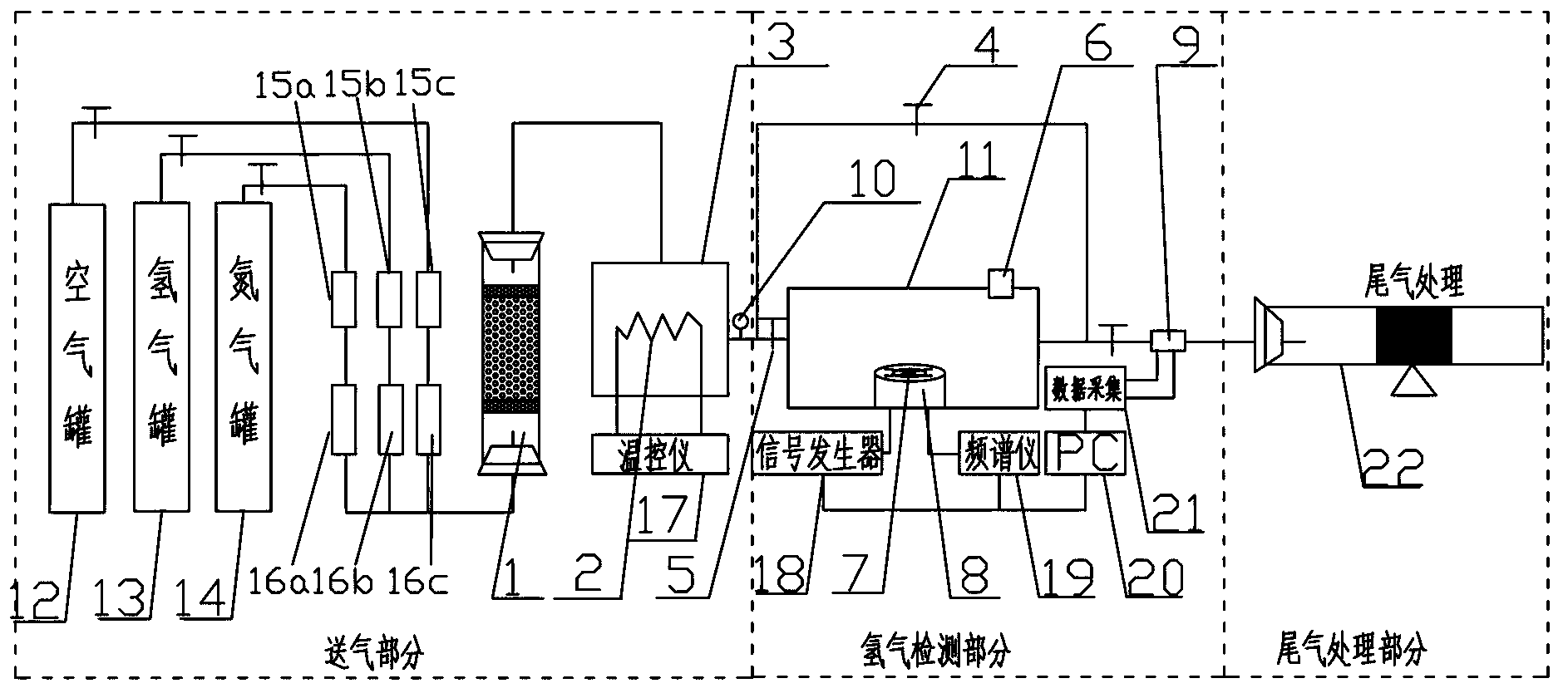
[0041] Such as figure 1 As shown, this embodiment discloses a hydrogen sensor testing system, which includes a gas supply part, a hydrogen detection part, and an exhaust gas treatment part.

[0042]The air supply part includes an air tank 12, a hydrogen tank 13, a nitrogen tank 14, a drier 1 and an air storage chamber 3, wherein the air tank 12, the hydrogen tank 13, and the nitrogen tank 14 are connected to the drier through pipelines, and the drier is connected to the gas storage room. The air tank 12, the hydrogen tank 13 and the nitrogen tank 14 each have control valves, and the pipelines between the air tank 12, the hydrogen tank 13, the nitrogen tank 14 and the drier 1 are respectively provided with pressure reducing valves 15a, 15b, 15c and mass Flow controllers 16a, 16b, 16c; a heater 2 controlled by a temperature controller 17 is arranged in the air storage chamber; the dryer 1 in the air supply part is composed of 2mm wire mesh and coke desiccant with 4 upper and lo...


PUM


Abstract

The invention discloses a hydrogen sensor testing system which comprises a gas supply part and a hydrogen detection part which are connected with each other, wherein the gas supply part comprises a hydrogen tank, a nitrogen tank, an air tank, a dryer and a gas storage chamber; the hydrogen tank, the nitrogen tank and the air tank are communicated to the dryer through pipelines; the dryer is communicated with the gas storage chamber; a heater controlled by a temperature controller is arranged in the gas storage chamber; the hydrogen detection part comprises an airtight chamber communicated with the gas storage chamber, a cylindrical platform in the airtight chamber, a signal generator, a spectrometer, a computer, a data acquisition card, and a tail gas analysis chamber communicated with the airtight chamber; the cylindrical platform is used for accommodating a gold ball bonding rack which is integrally connected with a sensor chip; the signal generator and the spectrometer are electrically, movably and respectively connected with the gold ball bonding rack and are also connected with the computer; a galvanic couple sensor and a gas flow sensor are arranged in the tail gas analysis chamber.

Description

technical field [0001] The invention relates to a hydrogen sensor testing system, more specifically to a testing system capable of controlling gas temperature, flow rate and pressure and testing by means of a frequency sweep method. Background technique [0002] With the rapid development of economy and technology at home and abroad, the consumption of energy is also increasing. Before oil is exhausted, finding a new energy to replace it has become the mainstream of scientific research. As an efficient and environmentally friendly energy source, hydrogen energy has naturally become the focus of attention. Although hydrogen energy has many advantages, it also has disadvantages. During the transportation, storage, and use of hydrogen, hydrogen leakage is very likely to occur. Hydrogen is colorless and odorless, and it is easy to mix with air and cause an explosion when it encounters an open flame. Traditional detection has defects such as high cost, long time-consuming, and ...

Claims


Application Information

Patent Timeline
Patent Type & Authority Applications(China)
IPC IPC(8): G01N29/02G01N29/30
Inventor 殷晨波顾春虎朱亚军朱斌杨柳
Owner NANJING UNIV OF TECH
Why Eureka
Try Eureka