Electric wire equipped with terminal fitting and method of manufacturing the same

a technology of electric wire and terminal fitting, which is applied in the direction of cable termination, connection contact material, cable junction, etc., can solve the problems of electric corrosion, aluminum having a strong ionization tendency to dissolve, and electric corrosion making progress

Inactive Publication Date: 2014-08-12
AUTONETWORKS TECH LTD +2
View PDF18 Cites 11 Cited by
  • Summary
  • Abstract
  • Description
  • Claims
  • Application Information

AI Technical Summary

Benefits of technology

[0010]In this configuration, an area from the exposed core wire to the coating continuing to this core wire is covered with the solder seal and the seal connection portion, thereby protecting the exposed core wire from water. Further, the space between the coating continuing to the exposed core wire and the solder seal are sealed by the seal connection portion, thereby preventing water from entering the solder seal. Then, the electric wire connection portion of the terminal fitting is crimped to the solder seal, whereby the core wire and the terminal fitting are electrically connected to each other.
[0011]At the crimping portion of the wire connection portion, the metal pieces having the close ionization tendencies come in contact with each other. Therefore, even when water attaches to the portion, electric corrosion hardly occurs. On the other hand, the solder seal and the core wire are made of the different kinds of metals; however, the portion where they come in contact with each other, that is, the solder seal is protected from water and, therefore, is not subject to electric corrosion. As a result, it is possible to securely prevent electric corrosion on the portion where the electric wire and the terminal fitting are connected to each other, without using anti-corrosive agents.
[0012]According to the present invention, it is possible to securely prevent electric corrosion on the portion where the electric wire and the terminal fitting are connected to each other, without using anti-corrosive agents.

Problems solved by technology

Therefore, when the electric wire is made of aluminum as above, electric corrosion occurs.
Therefore, this provides a possibility that aluminum having a strong ionization tendency dissolves, that is, electric corrosion makes progress.
This anti-corrosive applying method has a lot of problems including: necessity of changing application conditions depending on the shape in which the barrel is crimped; instability of quality due to fluctuations in thickness of an application; necessity of paying attention to the application layer not to be peeled off; and moreover, difficulty in repair at the time of maintenance.

Method used


Image

  • Electric wire equipped with terminal fitting and method of manufacturing the same
  • Electric wire equipped with terminal fitting and method of manufacturing the same
  • Electric wire equipped with terminal fitting and method of manufacturing the same

Examples


first embodiment

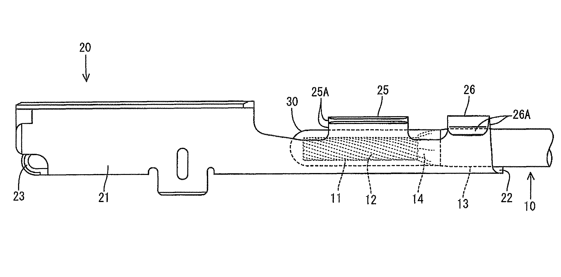
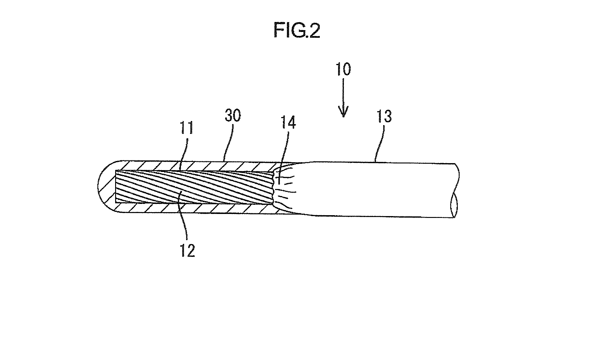
[0023]the present invention will be described with reference to FIGS. 1 to 6. The present embodiment exemplifies a configuration where the present invention is applied to an aluminum electric wire 10. The present invention exemplifies an aluminum electric wire equipped with a female terminal fitting including an aluminum electric wire 10, a female-side terminal fitting 20 (hereinafter referred to as female terminal fitting 20), a solder seal 30, and a seal connection portion 14 as shown in FIG. 3.

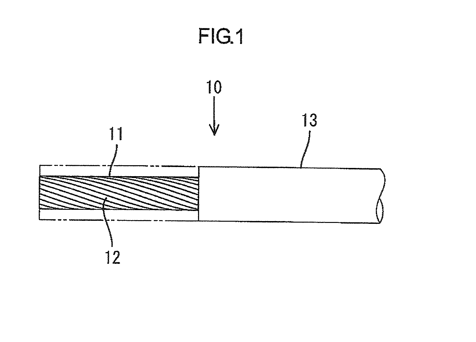
[0024]As shown in FIG. 1, the aluminum electric wire 10 has a configuration where a core wire 11 is formed of a twisted wire obtained by twisting a plurality of strands 12 made of aluminum or aluminum alloy and coated with an insulation coating 13 made of synthetic resin. The insulation coating 13 is made of resin, for example, synthetic resin including vinyl chloride (melting point: 180° C.), which can be welded thermally. The end of the insulation coating 13 of the aluminum electric wire ...

second embodiment

[0058]Although the second embodiment has squeezed and crimped the metal sleeve for sealing, the present invention is not limited to this. A heat shrinkable tube may be used as the sleeve to cover the core wire 11 and the insulation coating 13 to seal them off from each other.

[0059]The technology disclosed in the present description relates to an electric wire equipped with terminal fitting. The electric wire equipped with a terminal fitting includes: an electric wire including a metallic core wire coated with a coating; a terminal fitting made of a metal different from the metallic core wire; a solder seal formed of a solder containing a metal having an ionization tendency close to that of the terminal fitting as a main component; and a seal connection portion. The terminal fitting includes an electric wire connection portion connected to the electric wire. The solder seal seals an exposed portion of the metallic core wire that is exposed by removing a part of the coating of the ele...


PUM

PropertyMeasurementUnit
melting pointaaaaaaaaaa

Abstract

An aluminum electric wire (10) has a metallic core wire (11) coated with an insulation coating (13). A female terminal fitting (20) made of metal different from the core wire (11) has a wire barrel (25) to be connected to the aluminum electric wire (10). A solder seal (30) is formed of solder having a main component with an ionizing tendency close to that of the terminal fitting. The wire barrel (25) is crimped to the core wire (11) exposed by peeling off the insulation coating (13) of the aluminum electric wire (10) and partially sealed with the solder. A seal connection portion (14) connects the insulation coating (13), the exposed core wire (11) and the solder seal (30) to each other in a condition where the coating (13) and the solder seal (30) are sealed off from each other.

Description

BACKGROUND OF THE INVENTION[0001]1. Field of the Invention[0002]The present invention relates to an electric wire equipped with a terminal fitting and a method of manufacturing the electric wire equipped with a terminal fitting.[0003]2. Description of the Related Art[0004]In the recent years, aluminum electric wires have been used for reducing weight in the field of wire harnesses for use in an automobile. The aluminum electric wire has a configuration where a core wire obtained by twisting a plurality of aluminum strands is coated with an insulation coating. Thus, in the case to be used as a harness, a terminal fitting is connected to the end of the electric wire generally. Specifically, the end of the coating for the electric wire is peeled to expose the end of the core wire, a wire barrel (electric wire connection portion) provided on the terminal fitting is crimped to thus-exposed end of the core wire, and an insulation barrel provided in the rear of the wire barrel is crimped t...

Claims


Application Information

Patent Timeline
Patent Type & Authority Patents(United States)
IPC IPC(8): H01R4/70H01R43/05H01R4/18H01R4/20H01R4/62H02G15/02
CPCH01R4/20H01R4/70H01R4/185H01R4/62Y10T29/49192
Inventor MORIKAWA, SATOSHIKOBAYASHI, KAZUMASAOTSUKA, TAKUJISHIMODA, HIROKI
Owner AUTONETWORKS TECH LTD
Why Eureka
Try Eureka