
Method and system for spatial radio-frequency performance testing based on multiple-antenna system

a multi-antenna system and spatial radio-frequency technology, applied in the field of radio frequency testing technology, can solve the problem that the air performance of multi-antenna terminals cannot be evaluated in the traditional chamber

Inactive Publication Date: 2014-08-12
ZTE CORP
View PDF5 Cites 6 Cited by
  • Summary
  • Abstract
  • Description
  • Claims
  • Application Information

AI Technical Summary

Benefits of technology

Enables effective testing of multi-antenna terminals by simulating spatial signals and analyzing their performance, addressing the gap in international standards for MIMO system testing and ensuring compliance with communication quality standards.

Problems solved by technology

However, the over the air performance of multi-antenna terminals cannot be evaluated in the traditional chamber.

Method used


Image

  • Method and system for spatial radio-frequency performance testing based on multiple-antenna system
  • Method and system for spatial radio-frequency performance testing based on multiple-antenna system
  • Method and system for spatial radio-frequency performance testing based on multiple-antenna system

Examples


Embodiment Construction

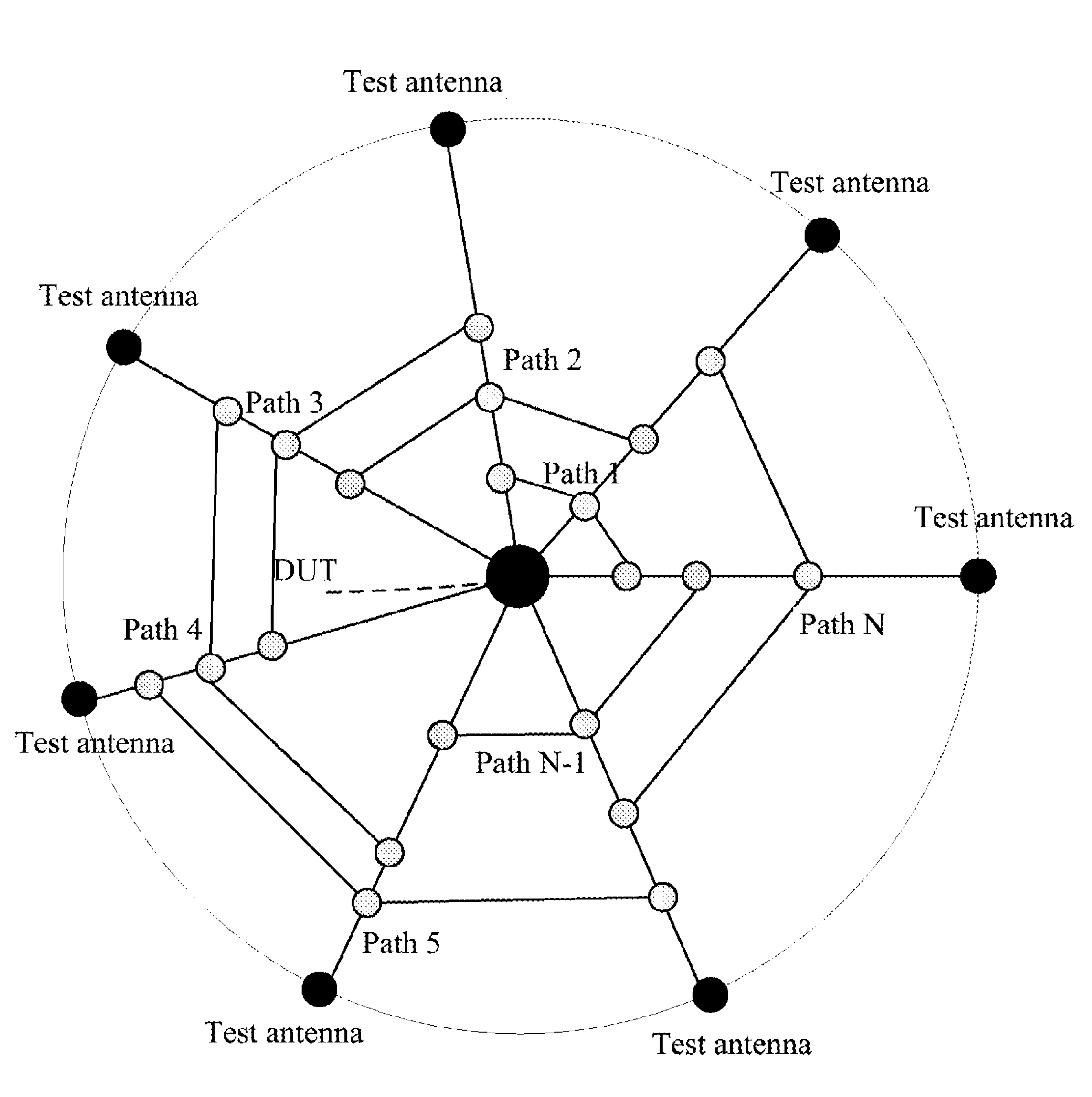
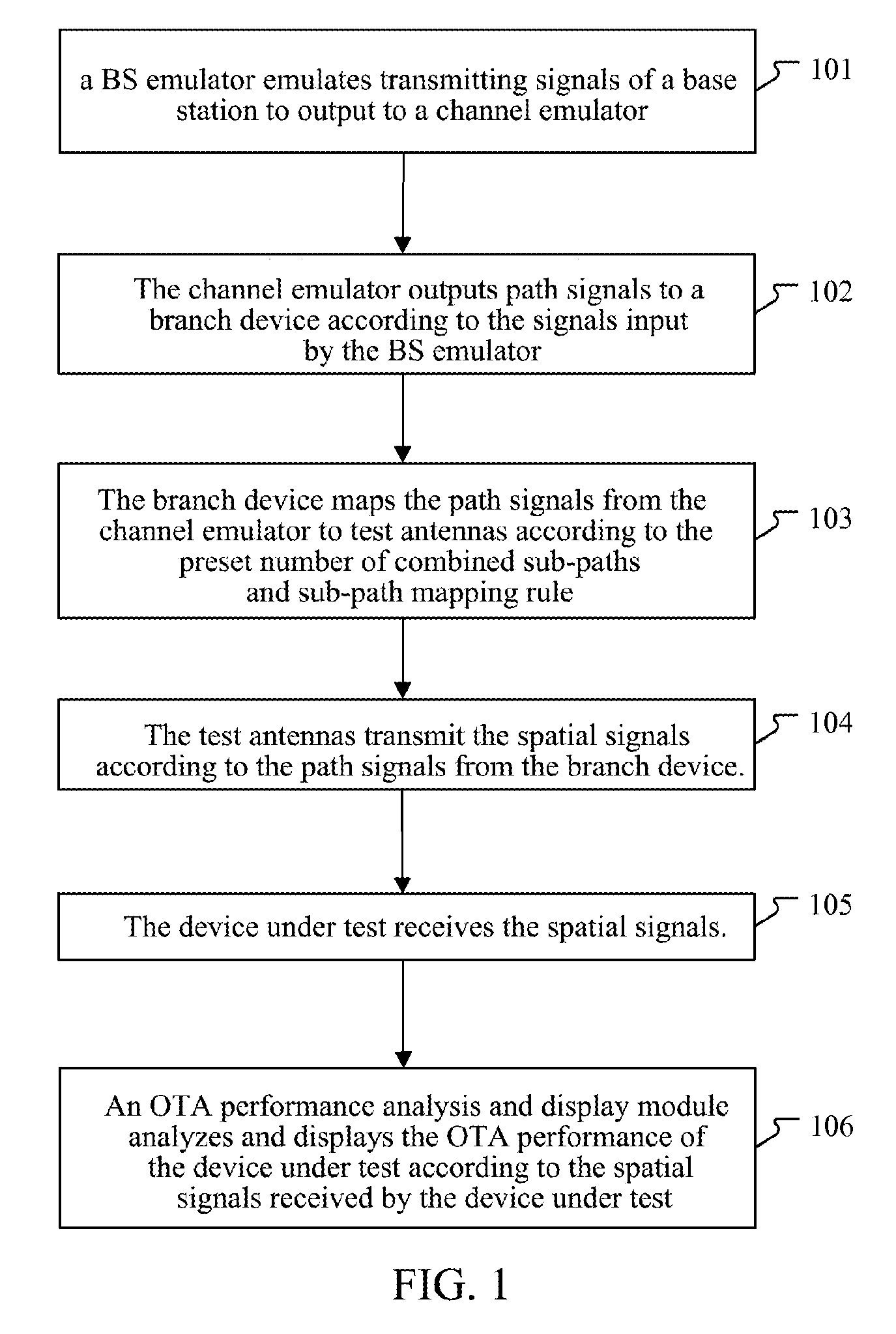
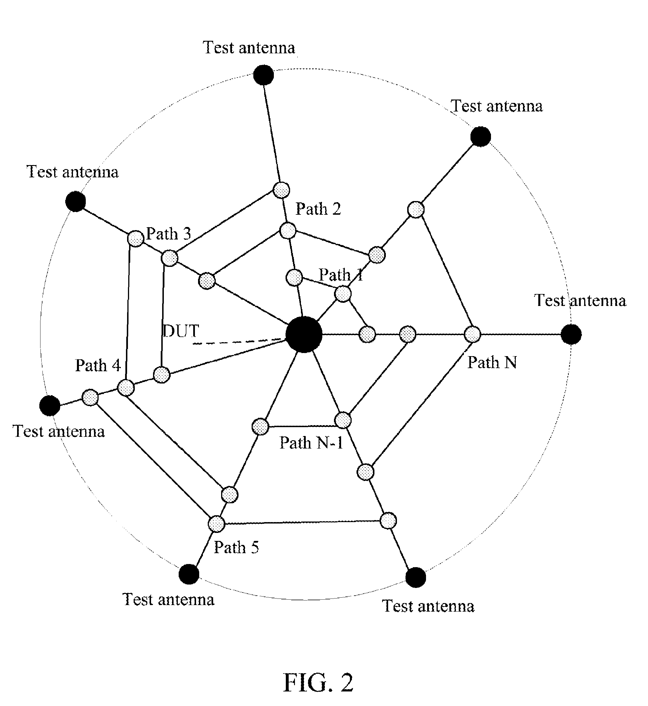
[0035]The basic idea of the present invention is that the path signals output by the channel emulator are mapped to the test antennas according to the preset number of combined sub-paths and sub-path mapping rule, the test antennas transmit the spatial signals according to the mapped path signals, and the over the air performance of the device under test is analyzed and displayed according to the spatial signals received by the device under test, thereby implementing test of the over the air performance of the multi-antenna terminal.

[0036]FIG. 1 is a flow diagram of a method for over the air performance testing based on a multi-antenna system according to the present invention. As shown in FIG. 1, the method for over the air performance testing based on the multi-antenna system according to the present invention generally comprises following steps.

[0037]In step 101, a base station (BS) emulator emulates transmitting signals of a base station to output to a channel emulator.

[0038]For...


PUM


Abstract

A method and system for over the air performance testing based on a multi-antenna system are disclosed. The method comprises: a branch device mapping path signals from a channel emulator to test antennas according to the set number of the combined sub-paths and sub-path mapping rule; the test antennas transmitting spatial signals according to the path signals from the branch device; and a device under test receiving the spatial signals; and an over the air performance analysis and display module analyzing and displaying the over the air performance of the device under test based on the spatial signals received by the device under test. The present invention implements the test of the over the air performance of a multi-antenna terminal.

Description

[0001]This application is a National Stage Application of PCT / CN2010 / 073908, filed 12 Jun. 2010, which claims benefit of Serial No. 201010109491.5, filed 12 Feb. 2010 in China and which applications are incorporated herein by reference. To the extent appropriate, a claim of priority is made to each of the above disclosed applications.TECHNICAL FIELD[0002]The present invention relates to radio frequency testing technology, and more particularly, to a method and system for over the air performance testing based on a multi-antenna system.BACKGROUND OF THE RELATED ART[0003]With the development of modern industry, among various wireless communication products, only those with good transmitting and receiving performance can guarantee communication quality, that is, total radiated power (TRP) is required to be greater than a certain value and total radiated sensitivity (TRS) is required to be less than a certain value, and in other words, over the air (OTA) performance test index is requir...

Claims


Application Information

Patent Timeline
Patent Type & Authority Patents(United States)
IPC IPC(8): H04B17/00
CPCH04B17/0087H04B17/008H04B17/0007H04B17/12H04B17/29
Inventor GUO, YANGZHENG, XINYUYU, ZHONG
Owner ZTE CORP
Learn More