
Magazine locking structure for gun

Inactive Publication Date: 2014-08-19
HU SHIH CHE
View PDF4 Cites 10 Cited by
  • Summary
  • Abstract
  • Description
  • Claims
  • Application Information

AI Technical Summary

Benefits of technology

The present invention is a magazine locking structure for a gun that solves the problems of previous designs. It makes it easier to install and dismount the magazine. This is the technical effect of the invention.

Problems solved by technology

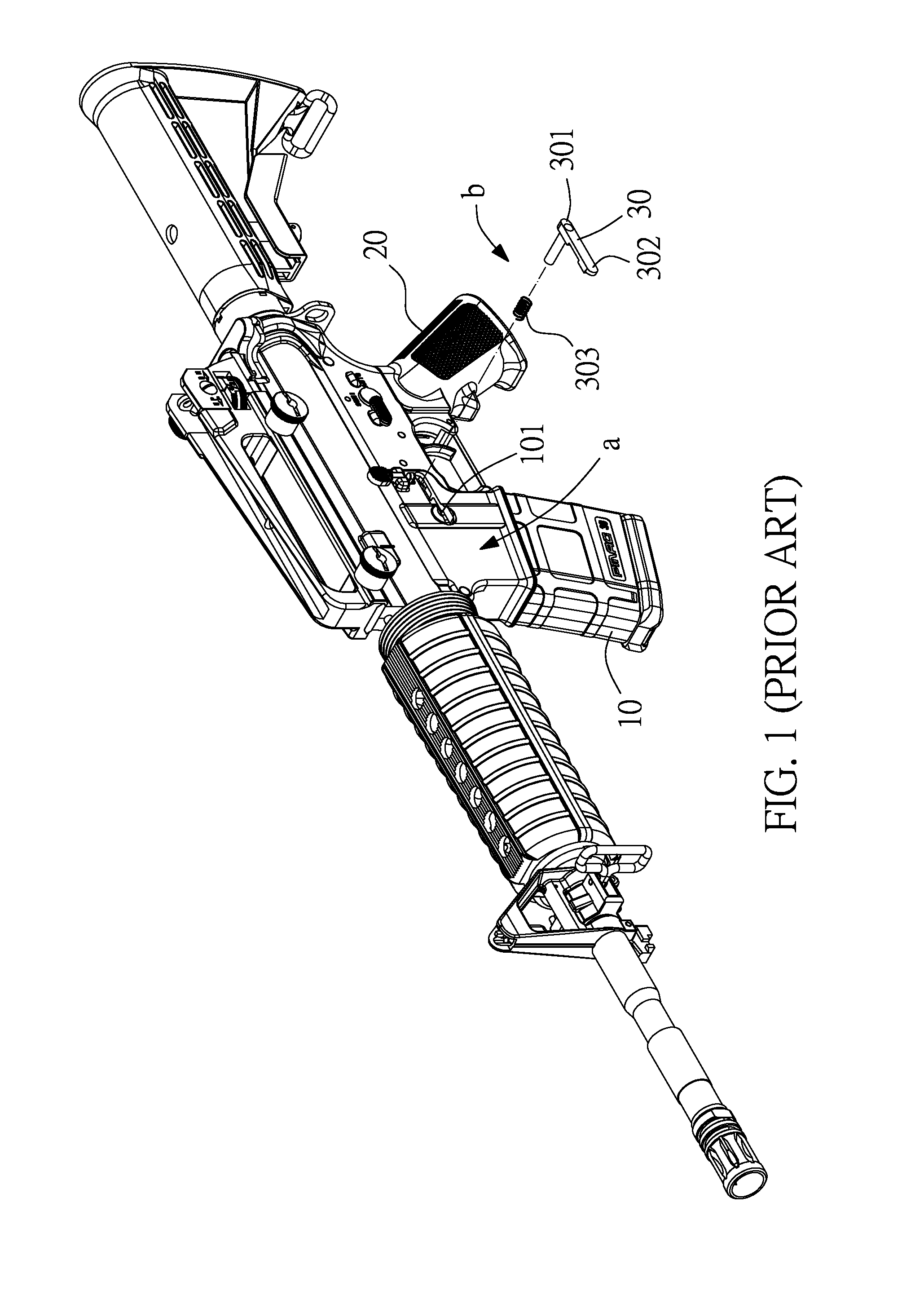
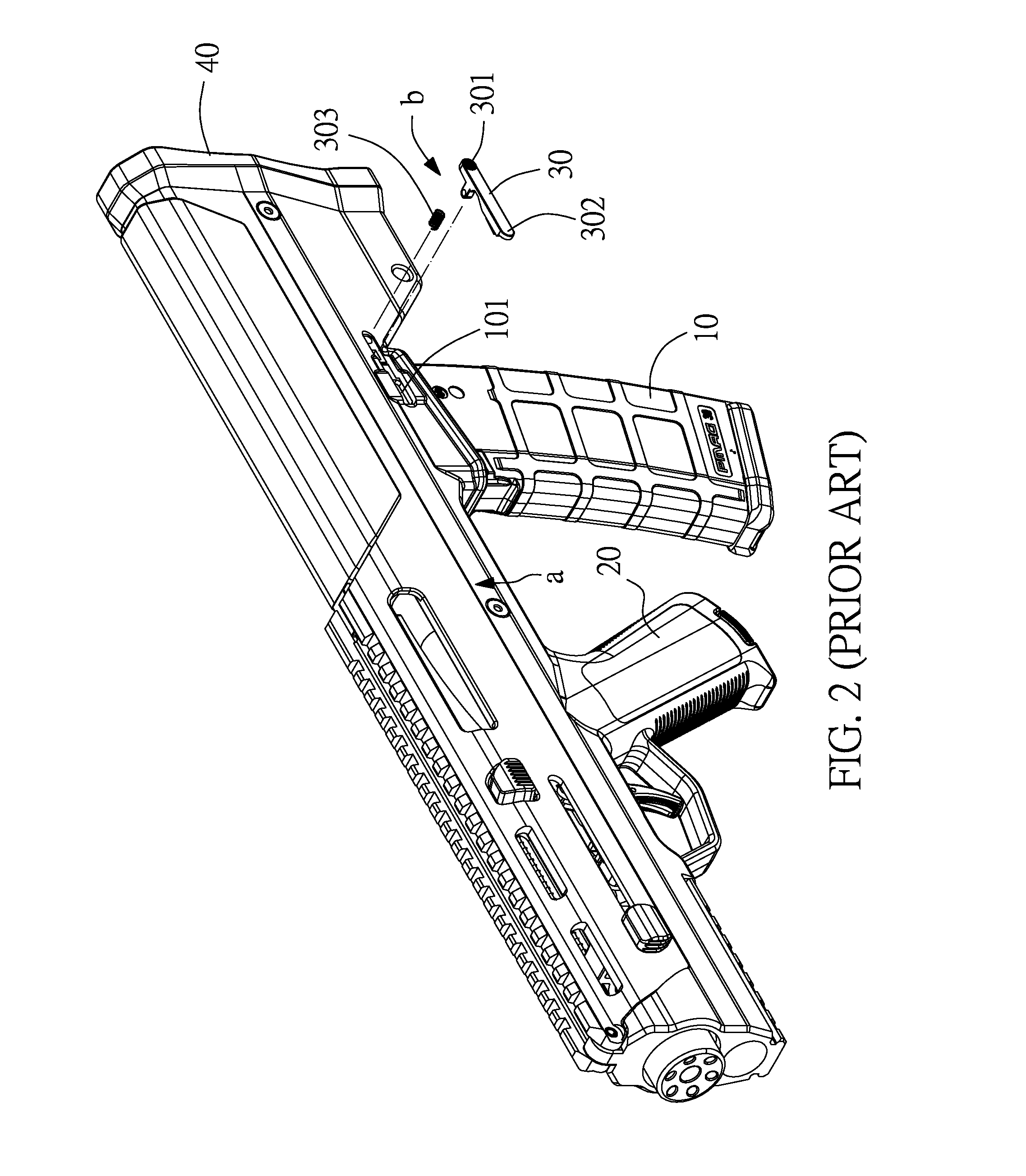
1. The magazine 10 is disposed near the rear gun butt 40 and kept near the user's body. Because the locking member 30 is not in the front sightline, the other hand (normally the left hand) of the user that is not holding the grip 20 cannot press the press rod portion 301 easily and rapidly when going to replace the magazine 10, complicating the magazine 10 mounting and dismounting procedures.
2. When going to replace the magazine 10, the user needs to put down the gun, and then pick up the gun for firing after replacement of the magazine 10. The application of this design of gun causes inconvenience and lacks mobility.

Method used


Image

  • Magazine locking structure for gun
  • Magazine locking structure for gun
  • Magazine locking structure for gun

Examples


Embodiment Construction

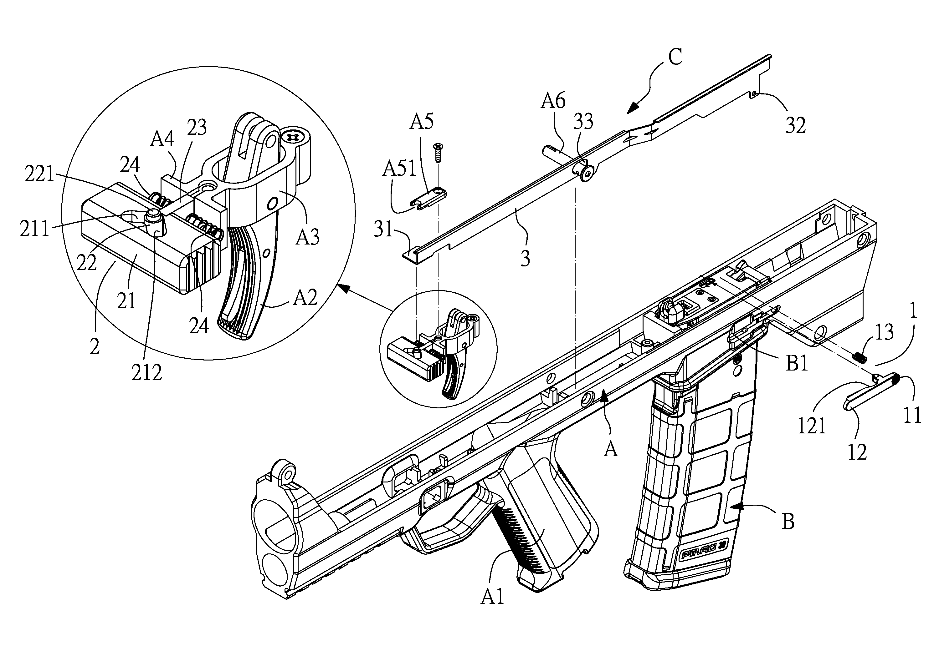
[0029]Referring to FIG. 3, a magazine locking structure C in accordance with the present invention is shown installed in a gun. The gun comprises a main gun body A and a magazine B. The main gun body A comprises a grip A1, a trigger A2 disposed at a front side relative to the grip A1 (see FIG. 4), a trigger holder A3 disposed around the top side of the grip A1 (see FIG. 3), a front block A4 fixedly located at the front side of the trigger holder A3, and a cover plate A5 connected to the top side of the front block A4. The cover plate A5 defines a notch A51 at the front side thereof. The magazine B is mounted in the main gun body A at a rear side relative to the grip A1, defining a retaining groove B1. Further, the magazine locking structure C comprises a locking member 1, a spring-loaded button set 2, and a link 3.

[0030]The locking member 1 (see FIG. 3) is mounted at one lateral side of the main gun body A adjacent to the magazine B, having two opposite ends thereof respectively ter...


PUM


Abstract

A magazine locking structure used in a gun is disclosed to include a locking member mounted in the main gun body behind the grip and pressable directly to unlock the magazine from the main gun body, a spring-loaded button set mounted in the main gun body in front of the grip, and a link coupled between the spring-loaded button set and the locking member for moving the locking member to lock or unlock the magazine when the user pushes a press block to shift an actuation rod leftward or rightward in moving a side lug of the link via a push block that is supported between two second spring members.

Description

NOTICE OF COPYRIGHT[0001]A portion of the disclosure of this patent document contains material which is subject to copyright protection. The copyright owner has no objection to any reproduction by anyone of the patent disclosure, as it appears in the United States Patent and Trademark Office patent files or records, but otherwise reserves all copyright rights whatsoever.BACKGROUND OF THE PRESENT INVENTION[0002]1. Field of Invention[0003]The present invention relates to gun technology, and more particularly to a magazine locking structure for gun, which allows the user to unlock the magazine from the gun by either a front operating mode or a rear operating mode.[0004]2. Description of Related Arts[0005]The magazine 10 of a big gun (see FIG. 1) is mounted at the main gun body “a” in front of the grip 20, and detachably secured to the main gun body “a” by a magazine locking device “b”. The magazine locking device “b” comprises a locking member 30 and a spring member 303. The locking me...

Claims


Application Information

Patent Timeline
IPC IPC(8): F41A9/61F41A17/38
CPCF41A17/38F41A9/61F41A9/65
Inventor HU, SHIH-CHE
Owner HU SHIH CHE
Learn More