Locking device including an installation handle for locking a hammer to a rotor in a horizontal shaft impact crusher

a technology of a locking device and a rotor is applied in the field of locking devices including an installation handle for locking a hammer to a rotor in a horizontal shaft impact crusher. it can solve the problems of requiring two fitters to apply, wear and replacement of hammers, and not being able to efficiently use labour. the effect of mounting and dismounting the hammer elements

Inactive Publication Date: 2019-07-04
SANDVIK INTELLECTUAL PROPERTY AB
View PDF0 Cites 3 Cited by
  • Summary
  • Abstract
  • Description
  • Claims
  • Application Information

AI Technical Summary

Benefits of technology

[0007]The invention seeks to provide a locking device that facilitates mounting and dismounting of hammer elements on to a HSI-crusher that mitigates at least one of the above problems, or at least provides an alternative arrangement to known locking devices.

Problems solved by technology

Due to the abrasive nature of the materials being crushed, the hammers wear and need to be replaced.
One problem with this approach is that it requires two fitters to apply.
This is not a very efficient use of labour.
A second problem with this approach is that the there is a significant health and safety risk for the fitter using the spanner since that fitter has to place his hands underneath the locking device and hammer.
If the hammer should slip out of a lifting tool, it would crush the fitter's hand, since each hammer is very heavy, typically around 800 kg.
Another problem with the prior art mounting device is that crushed rock can enter the central hole housing the screw element.
This can prevent the T-shaped turning tool from accessing screw element, which makes it very difficult to dismount the hammer from the rotor.
This problem has been addressed to some extent by inserting a plastic cap into the central hole to block the ingress of rock, however it has been found that the plastic cap often becomes dislodged during use of the crusher, which allows rock into the hole.

Method used


Image

  • Locking device including an installation handle for locking a hammer to a rotor in a horizontal shaft impact crusher
  • Locking device including an installation handle for locking a hammer to a rotor in a horizontal shaft impact crusher
  • Locking device including an installation handle for locking a hammer to a rotor in a horizontal shaft impact crusher

Examples


Embodiment Construction

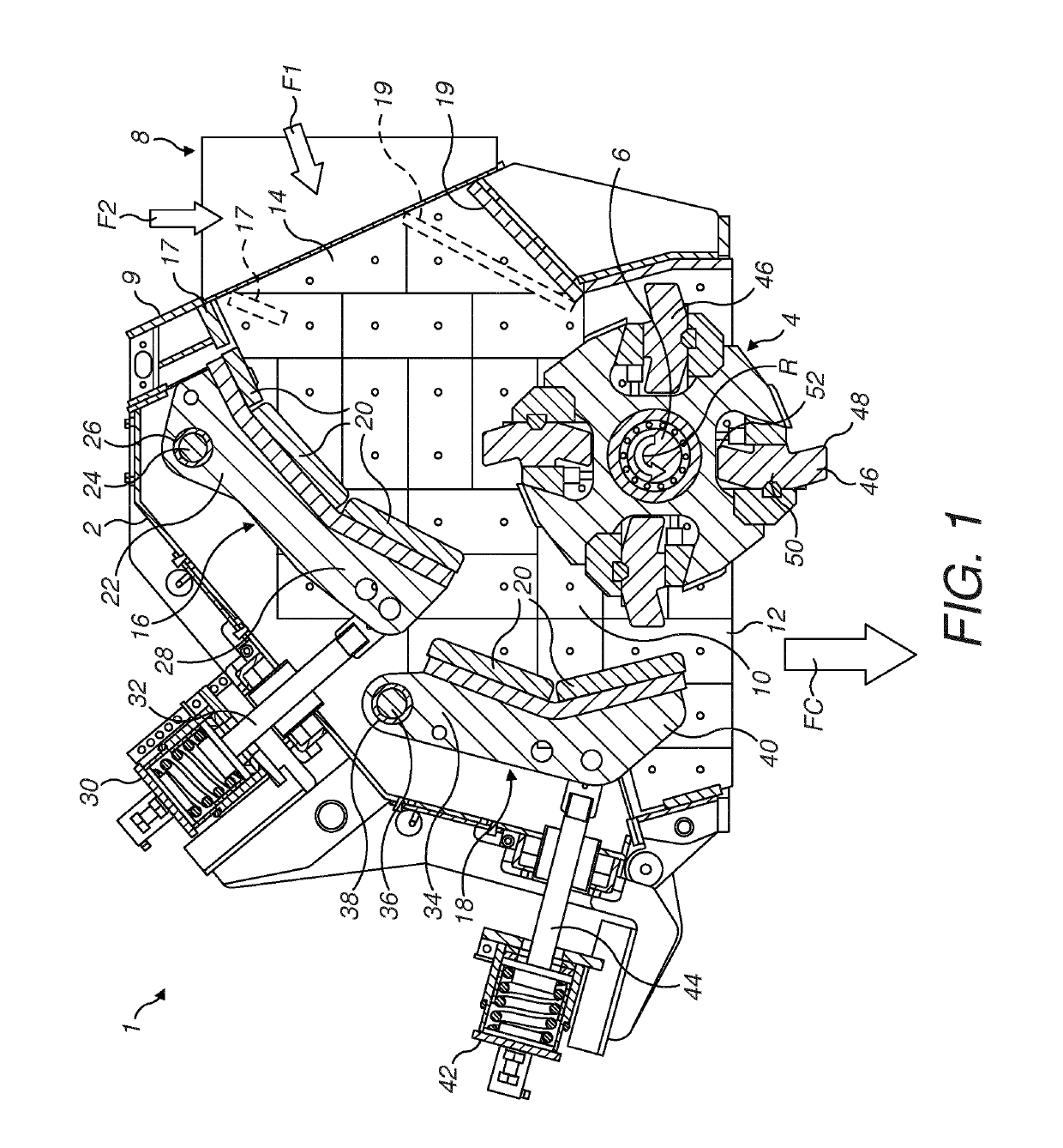
[0060]Referring to FIG. 1 a horizontal shaft impact crusher 1 (HSI-crusher) comprises a housing 2 in which a rotor indicated generally by reference 4 is rotatably mounted. A motor, (not illustrated) is operative for rotating a horizontal shaft 6 on which the rotor 4 is mounted. As an alternative to rotor 4 being fixed to shaft 6, rotor 4 may rotate around shaft 6. In either case, rotor 4 is operative for rotating around a horizontal axis, coaxial with the centre of shaft 6.

[0061]Material to be crushed is fed to a feed chute 8, which is mounted to an inlet flange 9 of housing 2, and enters a crushing chamber 10 positioned inside the housing 2 and at least partly enclosing the rotor 4. Material crushed within the crusher 1 exits the crushing chamber 10 via a crushed material outlet 12. Housing 2 is provided with a plurality of interior wear protection plates 14 operative for protecting the interior of crushing chamber 10 from abrasion and impact by the material to be crushed.

[0062]Cru...


PUM


Abstract

A locking device for a crusher rotor of a horizontal shaft impact crusher including at least one hammer element and at least one rotor disc having a plurality of rotor arms. The locking device includes a locking-wedge having a first engagement surface for engaging one of the rotor arms and a second engagement surface for engaging the hammer element. An installation handle of the locking devices is arranged to move the locking-wedge to a locking position where the first engagement surface engages the rotor arm and the second engagement surface engages the hammer element.

Description

FIELD OF INVENTION[0001]The present invention relates to a locking device for mounting and dismounting hammer parts on to a rotor of a horizontal shaft impact crusher (HSI-crusher), a HSI-crusher including at least one of the locking devices, and a method for assembling a crusher rotor.BACKGROUND ART[0002]Horizontal shaft impact crushers (HSI-crushers) are utilized in many applications for crushing hard material, such as pieces of rock, ore etc. A HSI-crusher comprises a crushing chamber housing a rotor (alternatively termed an impeller) that is driven to rotate about a horizontal axis. Pieces of rock are fed towards the rotor and are struck by rotor mounted hammer elements. The rock pieces are disintegrated initially by striking contact with the hammer elements and are then accelerated and thrown against breaker plates (typically referred to as curtains) to provide further disintegration. The action of the rotor causes the material fed to the horizontal shaft impact crusher to move...

Claims


Application Information

Patent Timeline
Patent Type & Authority Applications(United States)
IPC IPC(8): B02C13/28
CPCB02C13/2804B02C2013/2808B02C2210/02
Inventor DALLIMORE, ROWANFORSBERG, ANDREASKJAERRAN, KNUT
Owner SANDVIK INTELLECTUAL PROPERTY AB
Why Eureka
Try Eureka