Floor wiping mechanism for self-propelled floor cleaner

a floor cleaner and self-propelled technology, which is applied in the direction of floor scrubbing machines, carpet cleaners, cleaning equipment, etc., can solve the problems of manual cleaning of the floor, high labor intensity, and inability to clean the floor in this way, and achieve the optimal cleaning effect and simple structural arrangement

Inactive Publication Date: 2015-11-24
EGENPOWER
View PDF5 Cites 4 Cited by
  • Summary
  • Abstract
  • Description
  • Claims
  • Application Information

AI Technical Summary

Benefits of technology

[0007]The present invention has been accomplished under the circumstances in view. It is the main object of the present invention to provide a floor wiping mechanism for self-propelled floor cleaner, which has a simple structural arrangement and provides an optimal cleaning effect.

Problems solved by technology

To busy modern people, cleaning the floor in this way is undoubtedly a very time-consuming and laborious work.
However, people still need to manually clean the floor with the mop.
This manner is still labor-consuming.
This design of floor-mopping robot uses a DC gear motor to rotate a mop, and therefore, its structure is complicated.
This design of floor-wiping mechanism has the same drawback of complicated structure.
Further, it is also troublesome to detach the wiping cloth towel.

Method used


Image

  • Floor wiping mechanism for self-propelled floor cleaner
  • Floor wiping mechanism for self-propelled floor cleaner
  • Floor wiping mechanism for self-propelled floor cleaner

Examples


Embodiment Construction

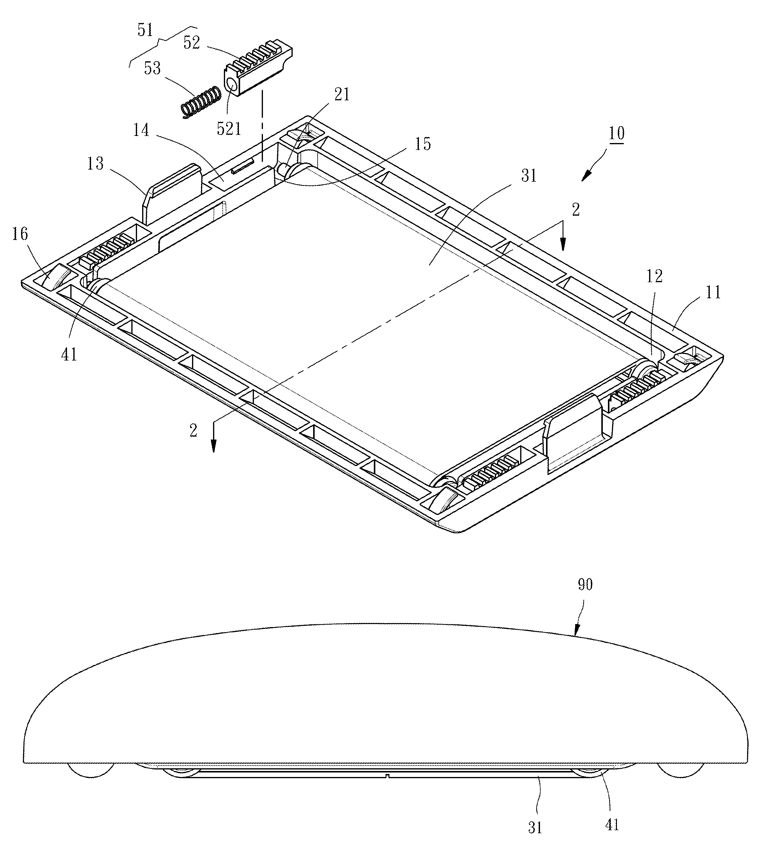
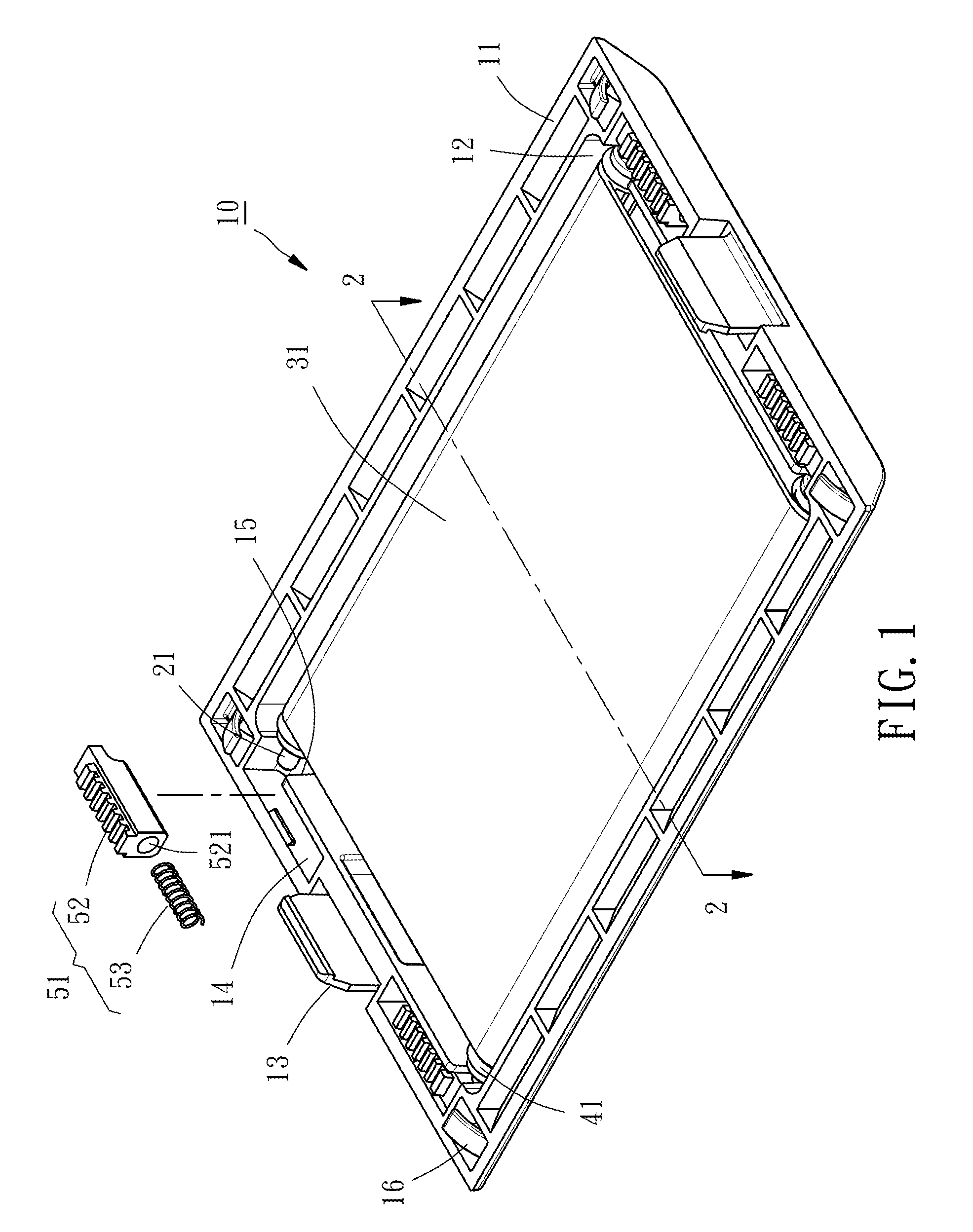
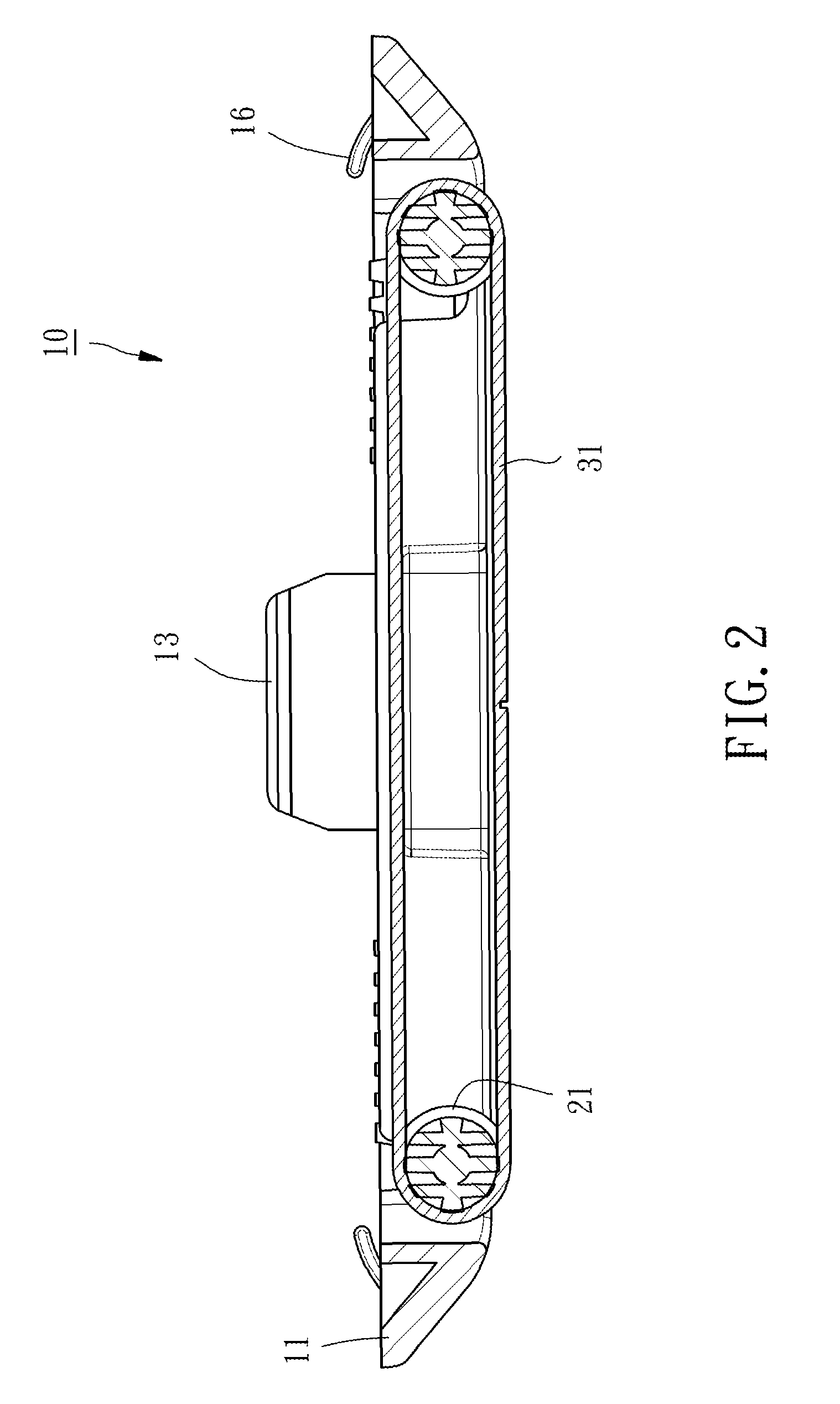
[0014]Referring to FIGS. 1-3, a floor wiping mechanism 10 in accordance with the present invention is shown mounted at a bottom side of a self-propelled floor cleaner body 90. The floor wiping mechanism 10 comprises a frame 11, two rotating shafts 21, a wiping cloth 31, four collars 41 and four pushing devices 51.

[0015]The frame 11 is a rectangular open frame, comprising an opening 12 located in the center thereof, at least two upright connecting portions 13 respectively located at two opposite lateral sides thereof and fastened to the self-propelled floor cleaner body 90 in such a manner that the bottom walls of the two opposite lateral sides of the frame 11 are kept at the same elevation, four accommodation chambers 14 located at the two opposite lateral sides in an opposite manner, and a notch 15 located in each accommodation chamber 14 in communication with the opening 12. In this embodiment, the frame 11 is configured to provide two upright connecting portions 13. In actual app...


PUM


Abstract

A floor wiping mechanism for mounting in the body of a self-propelled floor cleaner is disclosed to include a frame defining an opening, two rotating shafts suspending in the opening of the frame at two opposite lateral sides in a parallel manner with respective opposite ends thereof positioned in the frame, a wiping cloth made in the form of an endless belt and mounted around the two rotating shafts. When the self-propelled floor cleaner is steering, the floor wiping mechanism is moved with the self-propelled floor cleaner, causing the wiping cloth to wipe the floor.

Description

BACKGROUND OF THE INVENTION[0001]1. Field of the Invention[0002]The present invention relates to self-propelled floor cleaners and more particularly, to a floor wiping mechanism for mounting in the bottom side of the self-propelled floor cleaner body.[0003]2. Description of the Related Art[0004]In order to maintain a clean home environment, most people often use a broom and a dust mop to clean the floor. To busy modern people, cleaning the floor in this way is undoubtedly a very time-consuming and laborious work. So, there are many types of electric floor cleaners and self-propelled vacuum cleaners on the market. After cleaned the floor with an electric floor cleaner or vacuum cleaner, you must use a mop or drag to wipe the floor.[0005]Although there are many mop dewatering devices for allowing users to rapidly dewater the mop without wringing the mop with the hands. However, people still need to manually clean the floor with the mop. This manner is still labor-consuming.[0006]In or...

Claims


Application Information

Patent Timeline
Patent Type & Authority Patents(United States)
IPC IPC(8): A47L11/28A47L11/40A47L11/29
CPCA47L11/28A47L11/4036A47L11/4069A47L11/4047A47L11/29A47L11/00A47L2201/00
Inventor LI, GARYCHIU, YAO-HSI
Owner EGENPOWER
Why Eureka
Try Eureka