Image heating apparatus

Inactive Publication Date: 2011-03-10
CANON KK
View PDF1 Cites 9 Cited by
  • Summary
  • Abstract
  • Description
  • Claims
  • Application Information

AI Technical Summary

Benefits of technology

[0004]The primary object of the present invention is to provide an image heating apparatus which is simple in its structural a

Problems solved by technology

Thus, a fixing apparatus of the heat roller type suffers from the problem that as the fixation roller is rotated, the areas of the peripheral surface of the fixation roller, which are in contact with the abovementioned components, are likely to be scratched and/or frictionally worn, because the thermistor, parting claw, etc., are in contact with the peripheral surface of the fixation roller as described above.
This cr

Method used


Image

  • Image heating apparatus
  • Image heating apparatus
  • Image heating apparatus

Examples


embodiment 1

General Structure of Image Forming Apparatus

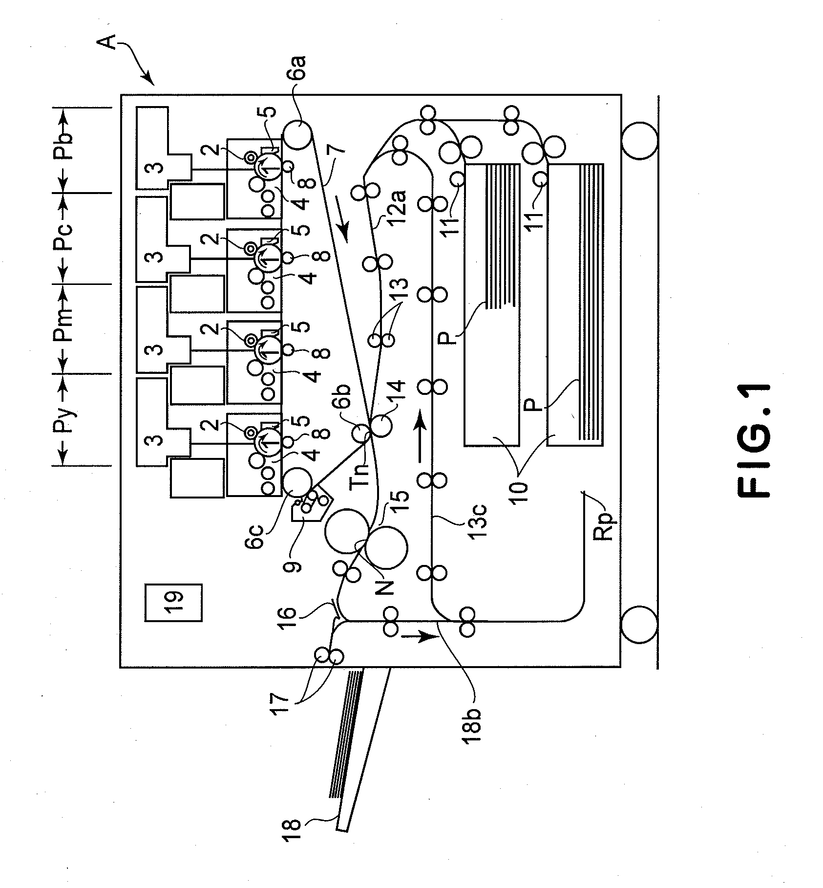
[0015]FIG. 1 is a schematic sectional view of a typical image forming apparatus in which an image heating apparatus in accordance with the present invention is mountable as a fixing apparatus (fixing device). It depicts the structure of the image forming apparatus. The image forming apparatus depicted in FIG. 1 is an electrophotographic full-color laser printer. The image forming apparatus A in this embodiment has the first, second, third, and fourth image forming portions Py, Pm, Pc, and Pb, which are in the main assembly of the apparatus and are in parallel with each other. The image forming apparatus A forms monochromatic toner images, different in color, by carrying out the processes of charging, exposing, developing, and transferring. Designated by a referential code 19 is a control portion as a controlling means, which is made up of a CPU, ROMs, RAM, etc. As a print command signal outputted from an external apparatus (unshown) such a...

embodiment 2

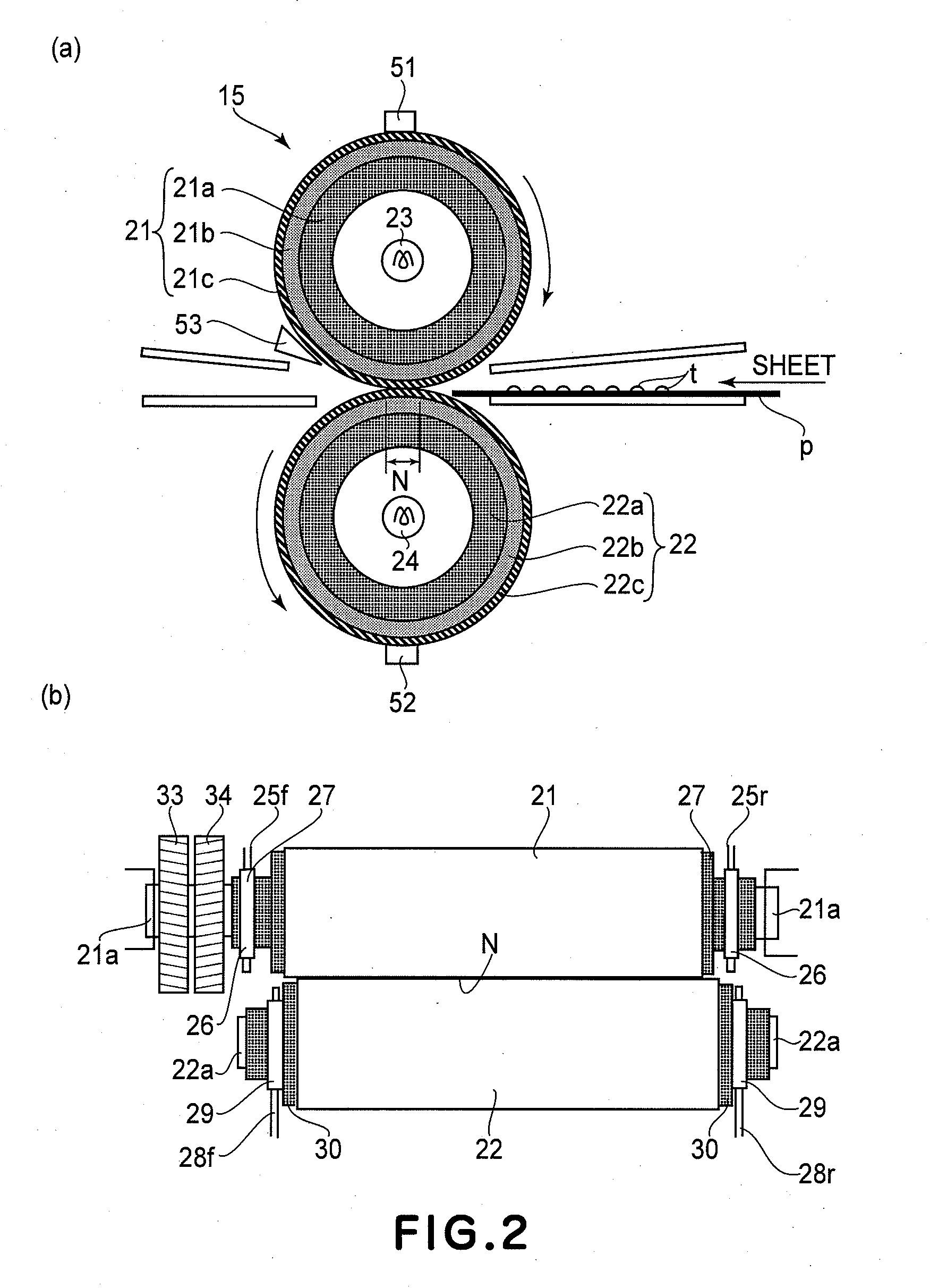
[0023]FIG. 6(a) is a schematic sectional view of the fixing apparatus in the second preferred embodiment of the present invention, and shows the structure of the apparatus. The members, portions, etc., of the fixing apparatus in the second embodiment, which are the same as the counterparts of the fixing apparatus 15 in the first embodiment, are given the same referential codes as those given to the counterparts and will not be described. In the case of the fixing apparatus 15 in the first embodiment, the first electromagnetic clutch CL1 and second electromagnetic clutch CL2 are turned on or off while the recording medium P is conveyed through the nip N during a printing operation. Therefore, the fixation roller 21 sometimes slightly changes in rotation speed as the first electromagnetic clutch CL1 and second electromagnetic clutch CL2 are turned on or off. The changes in the rotational speed of the fixation roller 21 sometimes results in the outputting of images which are nonuniform...

embodiment 3

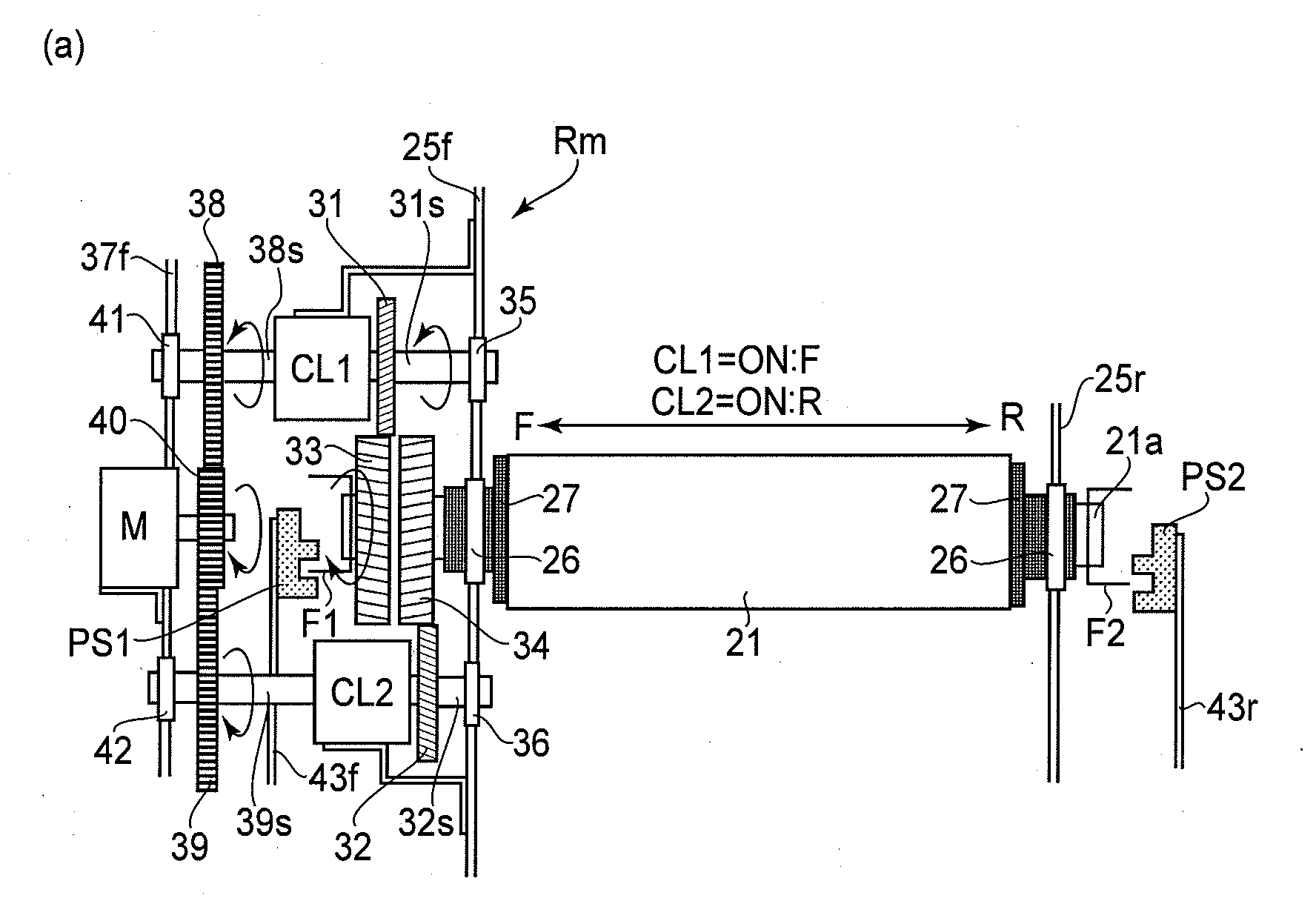
[0027]FIG. 8 is a schematic drawing of the fixing apparatus in the third embodiment of the present invention, and depicts the structure of another example of the fixation roller reciprocation mechanism. Also in the case of the fixing apparatus 15 in this embodiment, the members, portions, etc., of the fixing apparatus 15, which are the same as the counterparts of the fixing apparatus 15 in the first embodiment, are given the same referential codes as those given to the counterparts, and will not be described. In the case of the fixing apparatus 15 in the first embodiment, the third and fourth helical gears 33 and 34, respectively, are solidly attached to the lengthwise end portion of the metallic core 21a of the fixation roller 21, which is on the front side of the first top frame 25f. In the case of the fixing apparatus 15 in this (third) embodiment, the third helical gear 33 is solidly attached to one of lengthwise end portions, more specifically, the front end portion, of the met...


PUM


Abstract

An image heating apparatus comprising a heating rotatable member for heating an image on a recording material; a pressing rotatable member for contacting the heating rotatable member to form a nip therebetween; a driving source; a first helical gear rotatable by a driving force supplied from the driving source; a second helical gear rotatable by a driving force supplied from the driving source, the second helical gear has a twisting direction which is different from that of the first helical gear; a first switching member for switching between rotation transmission and non-transmission from the driving gear to the first helical gear; a second switching member for switching between rotation transmission and non-transmission from the driving gear to the second helical gear; a third helical gear provided on the heating rotatable member in meshing engagement with the first helical gear; a fourth helical gear provided on the heating rotatable member in meshing engagement with the second helical gear; and switching means for switching at least between drive transmission by first switching member and drive transmission by the second switching member to change a position of the heating rotatable member with respect to a rotational axis direction of the heating rotatable member.

Description

FIELD OF THE INVENTION AND RELATED ART[0001]The present invention relates to an image heating apparatus mountable in an image forming apparatus, such as an electrophotographic copy machine, an electrophotographic printer, or the like, to heat the image on recording medium.[0002]As one of the image heating apparatuses mountable in an image forming apparatus, such as an electrophotographic copy machine, an electrophotographic printer, or the like, a fixing apparatus of the heat roller type has been known. A fixing apparatus of the heat roller type has: a fixation roller; a heater for heating the fixation roller; a pressure roller which is pressed upon the peripheral surface of the fixation roller to form a nip; etc. Recording medium on which an unfixed toner image is present is heated while being conveyed through the abovementioned nip, remaining pinched by the fixation roller and pressure roller, whereby the image on the recording medium is thermally fixed to the recording medium. A ...

Claims


Application Information

Patent Timeline
IPC IPC(8): G03G15/20F16H1/08
CPCY10T74/19953G03G2221/1657G03G21/1647G03G15/2064G03G21/1685
Inventor SUZUKI, KENJI
Owner CANON KK
Why Eureka
Try Eureka