Multi-axis spring damping system for a payload in a spacecraft

a multi-axis spring and payload technology, applied in the direction of spring/damper functional characteristics, shock absorption, machine supports, etc., can solve the problems of cumbersome and costly, complex mounting system, and large cost of known mounting system, so as to reduce low frequency oscillating or vibrating loads, simple structural arrangement, and facilitate adjustment

Inactive Publication Date: 2009-11-12
AIRBUS DEFENCE & SPACE
View PDF18 Cites 24 Cited by
  • Summary
  • Abstract
  • Description
  • Claims
  • Application Information

AI Technical Summary

Benefits of technology

[0007]With such a spring damping element, and especially an arrangement of a plurality of such spring damping elements forming a spring damping system that mounts a payload-carrying pallet to a load platform as a support structure, it becomes possible to damp and reduce low frequency oscillating or vibrating loads in three axes, with a very simple structural arrangement of the damping element. Namely, each individual spring damping element provides a resilient damped force transmission in three orthogonal spatial axes (particularly in the axial direction of the bolt shaft and in all radial directions relative to the bolt shaft axis), and additionally in a torsional direction around the bolt shaft axis. A plurality of the damping elements forming the damping system can be mounted with their respective axes all parallel to one another, or with various damping elements oriented in different axial directions to achieve different compound damping effects. The torsional damping of an individual element is generally blocked or checked by the additional mounting of the pallet via additional damping elements on other offset parallel axes or non-parallel axes.
[0008]A particularly simple embodiment involves the spring damping cushion members comprising or made of a metal braid material with fibers of wire strands, or stranded wire, or cord strands. Generally, the damping cushion members must comprise an axially and radially yielding or resilient material with a damping effect due to internal friction.
[0009]According to a further embodiment of the invention, the intermediate caps that receive the inner ends of the spring damping cushion members and connect the spring damping element to the counter support of the pallet are provided with bolt receiving openings especially in the form of through holes with a larger diameter than the bolt shaft so as to form a radial spacing gap around the bolt shaft. Thereby, a direct contact of the bolt shaft and the intermediate caps is prevented, which ensures the radial spring-damped mounting function, and also facilitates the adjustment. On the other hand, the spring damping cushion members are each provided with a central hole that may fit closely or snugly onto the bolt shaft to ensure a direct radial force transmission between the bolt shaft and the damping member. Alternatively, the spring damping cushion members may have central axial holes larger than the bolt shaft diameter, whereby the radial force transmission is carried out partially by shearing forces through the damping cushion members between the intermediate caps and the receiver caps.
[0010]To provide additional pre-stressing or pre-compression of the spring damping element, and to improve the linearity of the response characteristic of the spring damping element by at least partially compensating a non-linearity of the spring damping cushion members, the spring damping element preferably further includes cupped disk springs and disk elements such as spacer disks or washers arranged in series with the spring damping cushion members respectively between the receiver caps and the intermediate caps.
[0011]According to a further preferred feature of the invention, the receiver caps and the intermediate caps each comprise an annular disk plate as well as a cylindrical cup wall that receives a respective end portion of the respective spring damping cushion member inserted partially therein. The axial height of the rims or cylindrical cup walls of the receiver caps and the intermediate caps is dimensioned to properly adapt the radial stiffness of the spring damping cushion members to the requirements of the particular application. Namely, the spring damping element will have a greater stiffness of its damping characteristic in the radial direction when the cylindrical cup walls are higher or axially longer, and on the contrary the radial stiffness will be reduced when the cylindrical cup walls have a reduced axial dimension.

Problems solved by technology

However, it has been found that the known arrangement of the known spring damping system is relatively complex, cumbersome and costly especially for damping very low frequency vibrations or motions of the received payload, because the known embodiment of the spring damping system is designed to also fulfill further requirements.
Therefore, to simply fulfill the multi-axis spring damping requirements, the known mounting system is more complicated and costly than it needs to be.

Method used


Image

  • Multi-axis spring damping system for a payload in a spacecraft
  • Multi-axis spring damping system for a payload in a spacecraft

Examples


Embodiment Construction

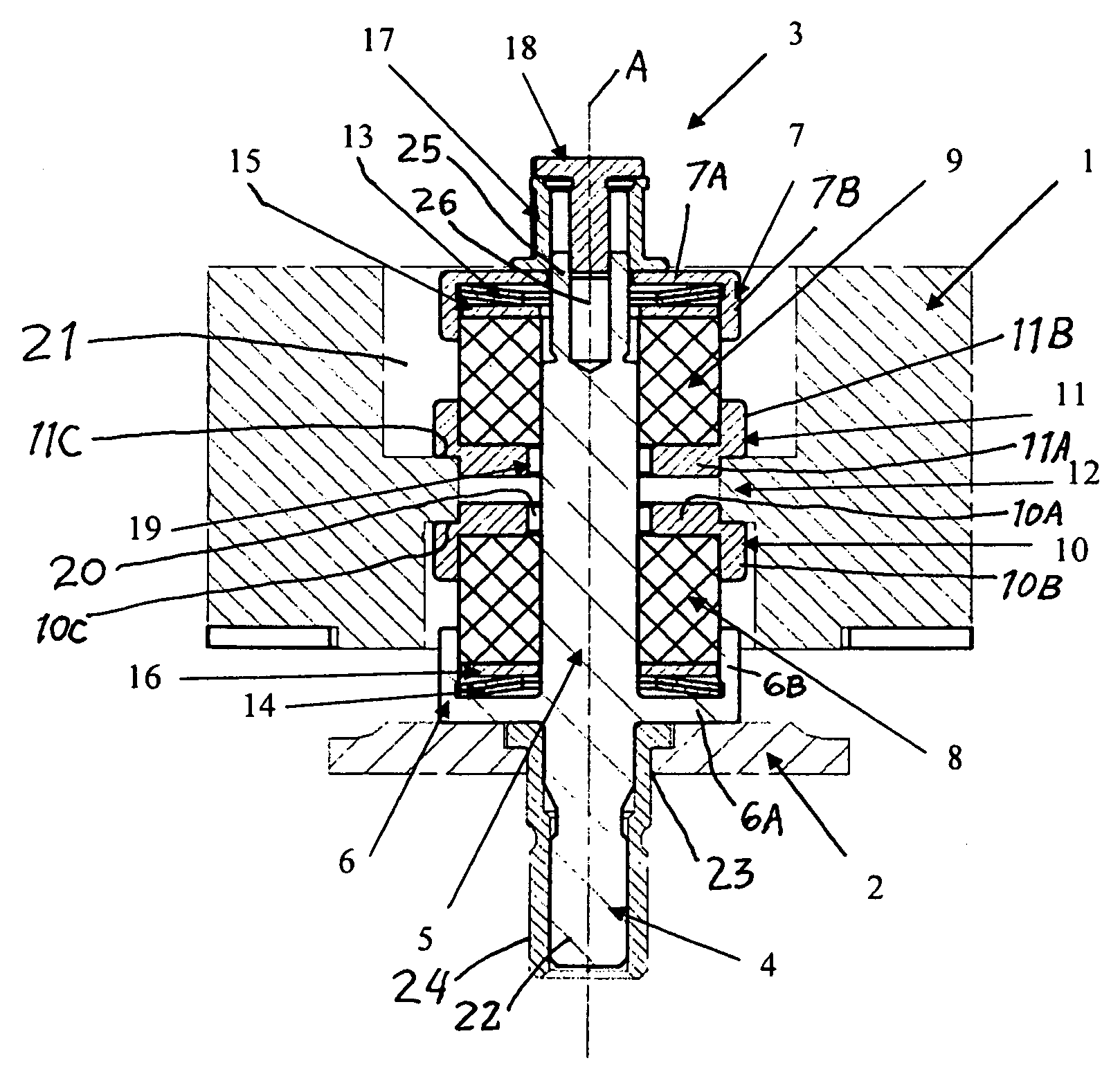
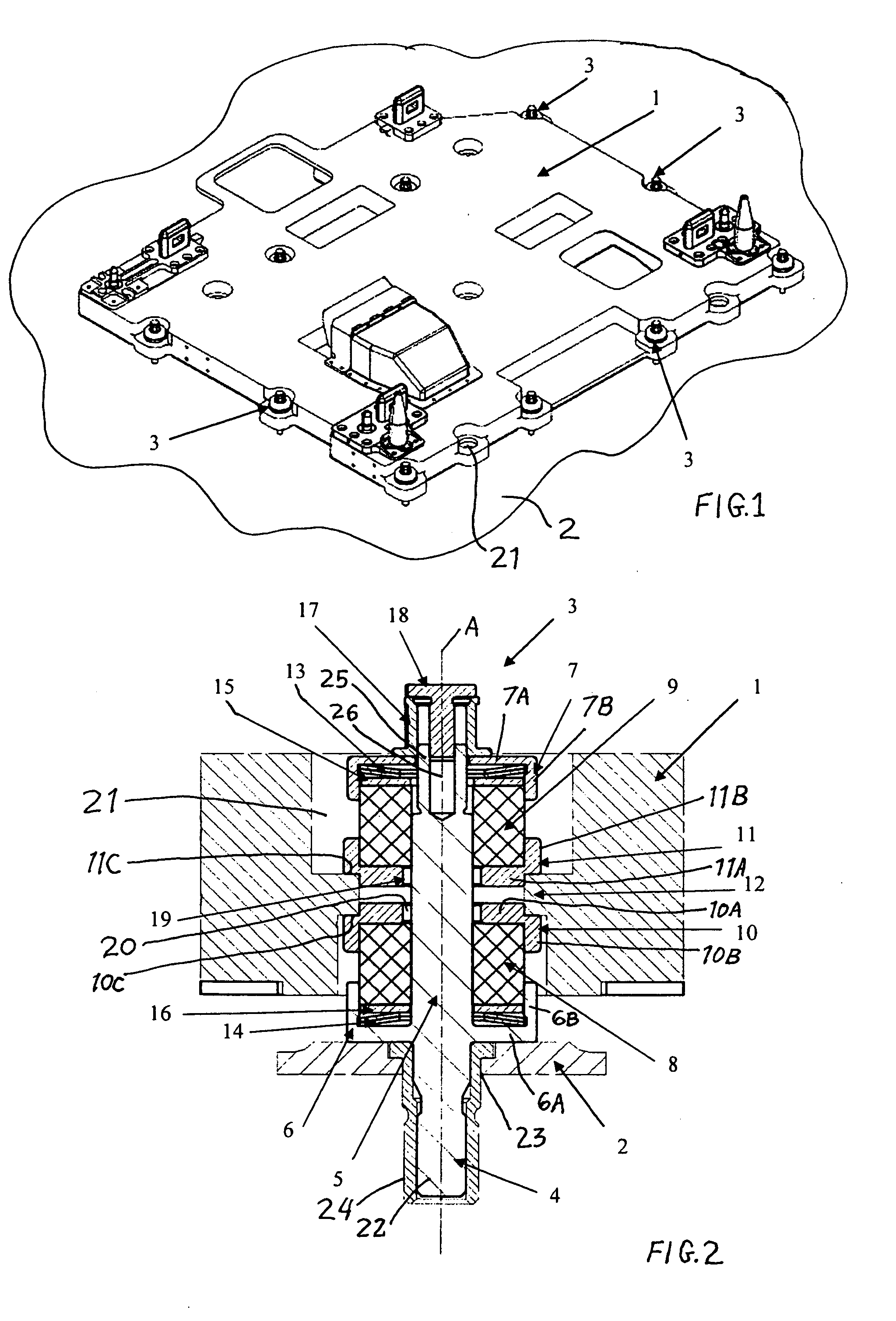
[0015]A preferred example embodiment of the present invention relates to a spring damping system for damping low frequency vibrations or oscillations in the payload carrying system in a space shuttle. A payload is mounted on or carried by a pallet 1 as shown in FIG. 1, and the pallet 1 is to be mounted on a load platform 2 as a support structure of the space shuttle by a plurality of spring damping elements 3 forming a spring damping system between the payload-carrying pallet 1 and the support structure or load platform 2.

[0016]As shown in greater detail in FIG. 2, each spring damping element 3 comprises a bolt 4 including a bolt shaft 5 having a first bolt end stub 22 that is received and secured in a mounting hole 23 in the load platform 2, for example with an interposed securing fixture or adapter sleeve 24. This arrangement connects a force output or input end of the spring damping element 3 to the load platform 2. The bolt shaft 5 extends upwardly from the load platform 2 along...


PUM


Abstract

A multi-axis spring damping element includes two spring damping cushion members received between caps on a bolt shaft, and an axial adjustment mechanism at a free end of the bolt shaft. The other end of the bolt shaft is connected to a support structure, and a load to be supported in a vibration-damped manner is carried by intermediate caps between the two spring damping cushion members. A plurality of such spring damping elements forms a spring damping system, for example for supporting a payload-carrying pallet on a load platform of a spacecraft.

Description

PRIORITY CLAIM[0001]This application is based on and claims the priority under 35 U.S.C. §119 of German Patent Application 10 2008 022 467.7, filed on May 7, 2008, the entire disclosure of which is incorporated herein by reference.FIELD OF THE INVENTION[0002]The invention relates to a spring damping element and a spring damping system including a plurality of such spring damping elements, which is especially suited for mounting a payload-carrying pallet, for example on a load platform as a support structure in a spacecraft.BACKGROUND INFORMATION[0003]In various fields of application, and especially in various transport fields, it is necessary to securely mount a payload to a support structure, such as a support structure of the transporting vehicle. Because of motions, accelerations and vibrations arising during transport of the payload, it is further necessary that such a mounting arrangement is able to provide spring damping of the arising loads, preferably in multiple axes, and e...

Claims


Application Information

Patent Timeline
Patent Type & Authority Applications(United States)
IPC IPC(8): F16F15/04
CPCB64G1/14F16F2228/08F16F15/046B64G1/641
Inventor RETAT, INGOABDOLY, KIYOUMARSKOEHLER, HORSTTRITSCH, WOLFGANG
Owner AIRBUS DEFENCE & SPACE
Why Eureka
Try Eureka