Method for producing a slab trackway

a technology of slab track and production method, which is applied in the direction of railway track, track maintainence, ballastway, etc., can solve the problems of high local wear of plates, uneconomical to keep a stock of prefabricated plates, and the dimensions of plates have to be adapted, so as to achieve quick setup and removal, convenient use, and convenient storage

Active Publication Date: 2015-10-13
SONNEVILLE
View PDF5 Cites 2 Cited by
  • Summary
  • Abstract
  • Description
  • Claims
  • Application Information

AI Technical Summary

Benefits of technology

[0017]The invention further relates to formwork elements for implementing the method of the invention. The main object of these elements is to allow a quick setup and removal.
[0018]According to the invention, this object is achieved in that the formwork elements consist of hoods that are intended to be fitted over parts of the sleepers and of plates connecting adjacent hoods. These hoods and plates are quickly mountable and dismountable and are furthermore reusable.
[0019]According to one embodiment of the formwork elements, the plates are removably connectable to the hoods. This measure also facilitates the mounting and dismounting of the formwork elements.
[0020]According to a further embodiment of the formwork elements, the plates are connectable to the hoods such that the spacing between adjacent hoods is variable. This eliminates the need for providing plates of different lengths in accordance with different sleeper spacings.

Problems solved by technology

However, a disadvantage is that the dimensions of the plates have to be adapted to the gauge, the sleeper block dimensions, the sleeper block spacing, and the slope of the filling concrete track slab.
All these variable parameters make it uneconomical to keep a stock of prefabricated plates.
A further disadvantage of emergency pathways of this kind is that the plates often do not rest stably on the filling concrete track slab so passing vehicles cause a tilting movement and the plates are thus subject to high local wear.

Method used


Image

  • Method for producing a slab trackway
  • Method for producing a slab trackway
  • Method for producing a slab trackway

Examples


Embodiment Construction

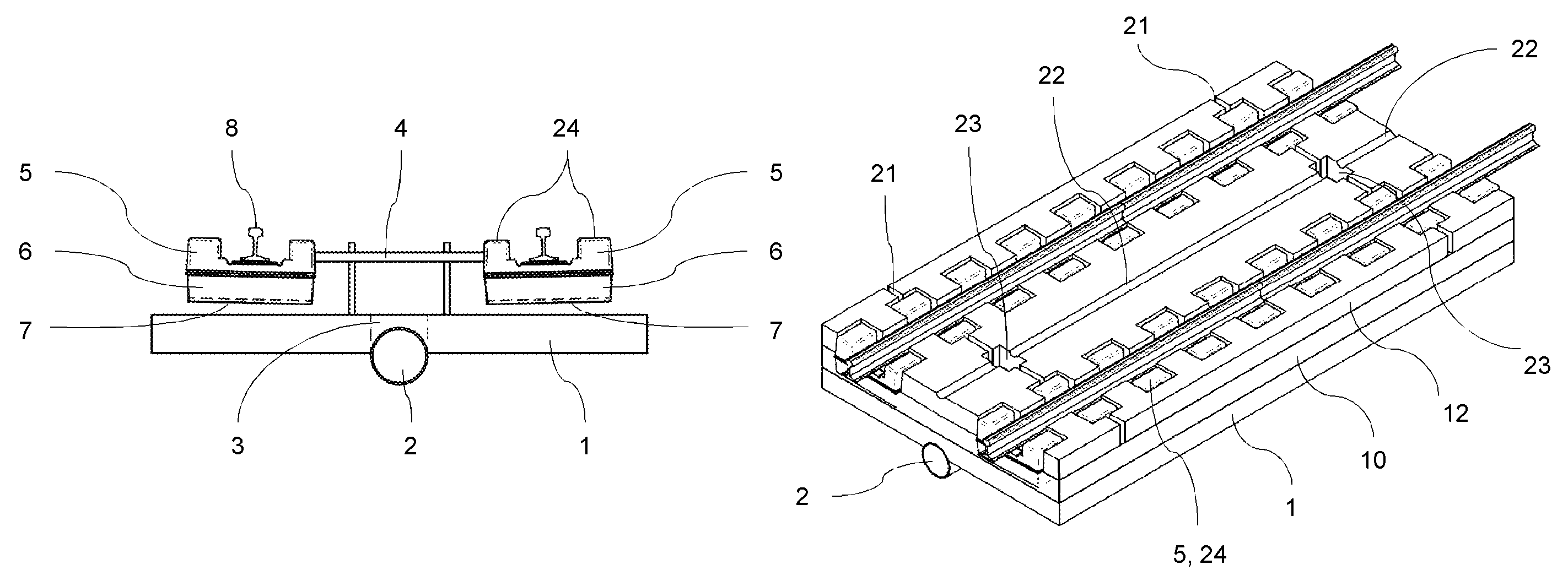
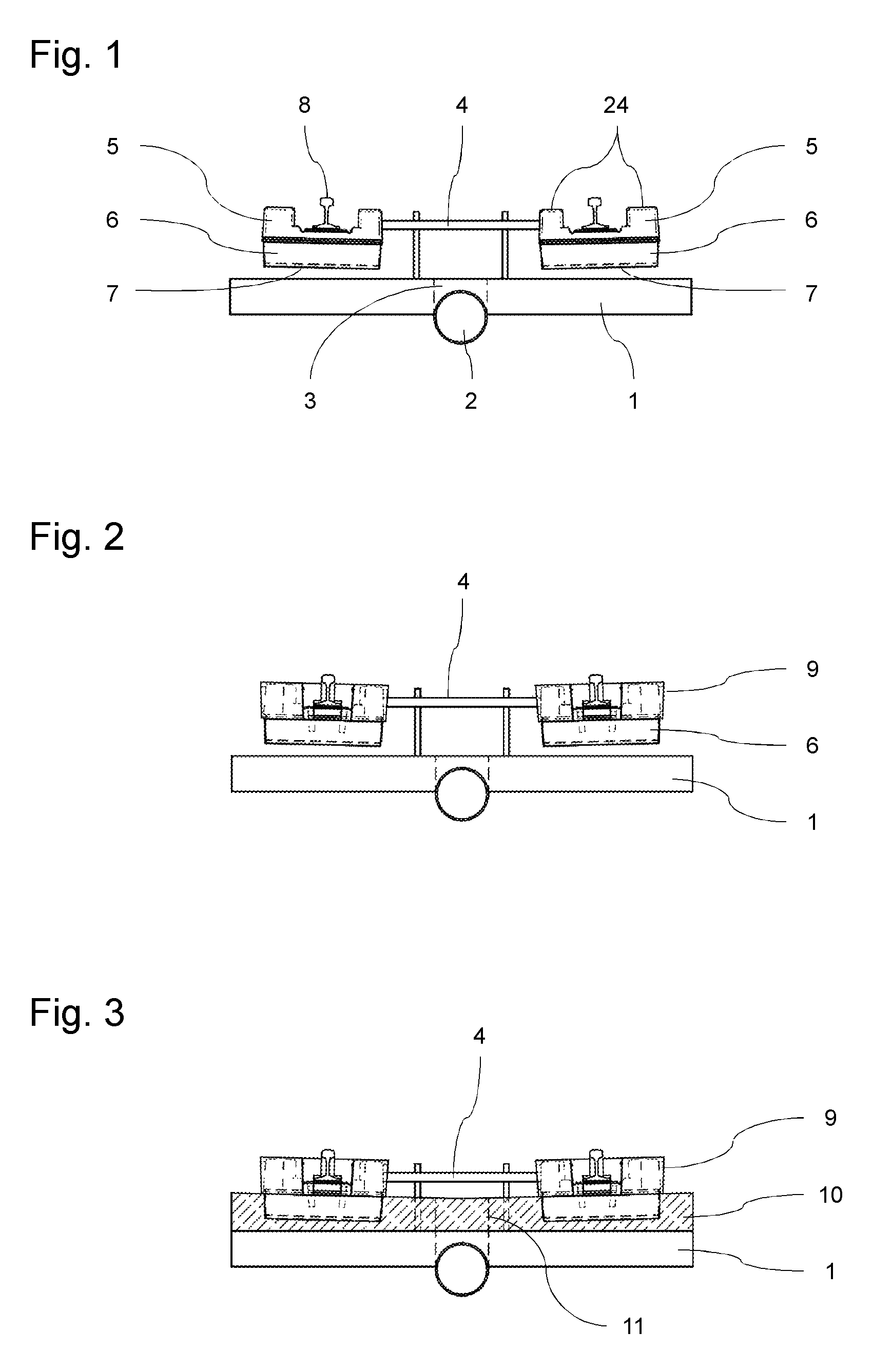
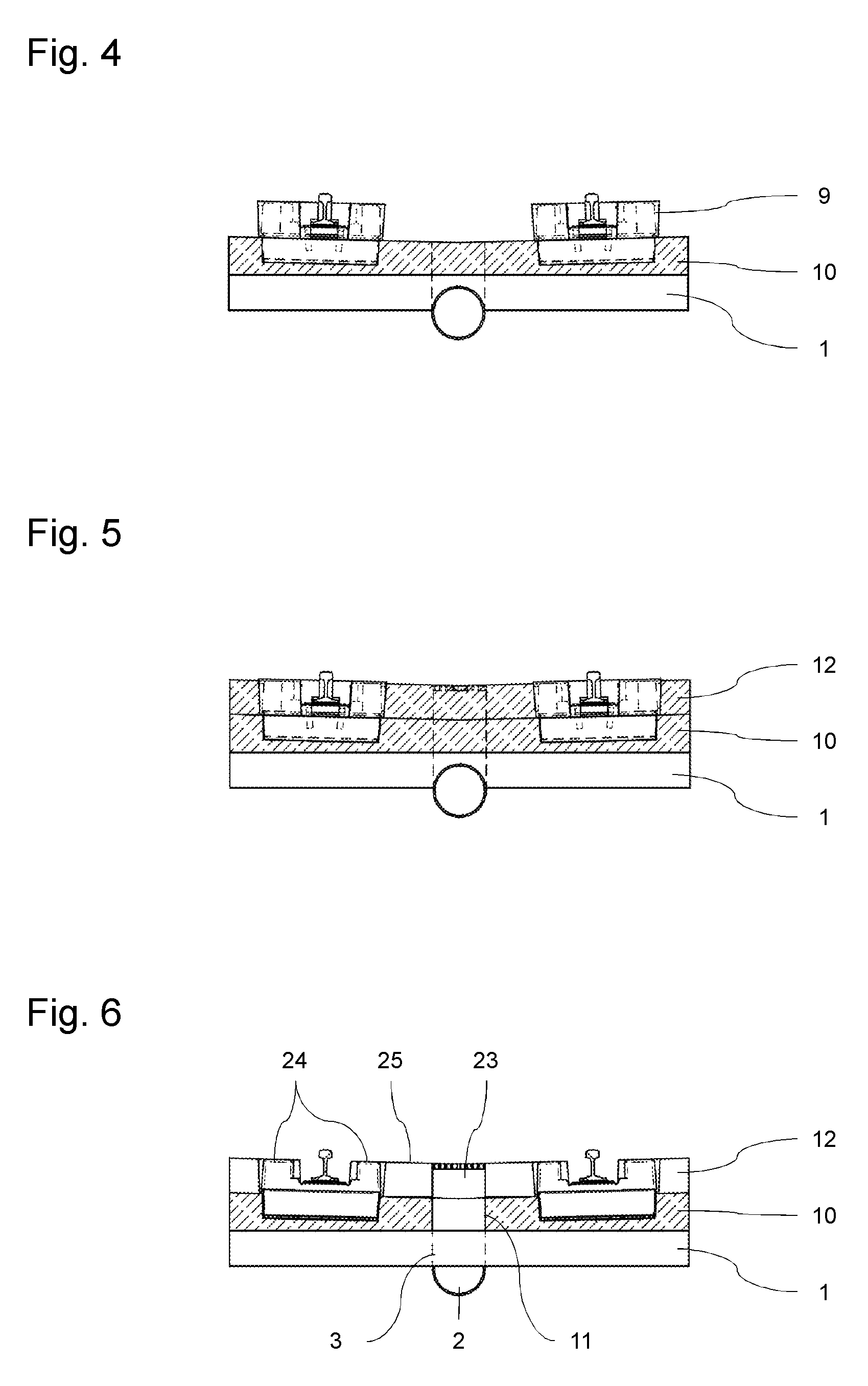
[0026]In FIG. 1, the initial situation in an embodiment of the method according to the invention is illustrated by way of example. A track section comprising a plurality of sleeper blocks 5 and of rails 8 mounted thereon is supported and aligned on a substructure 1, e.g. of reinforced concrete, by means of a supporting and aligning device 4. In the substructure extends a drainpipe 2 that communicates with the upper side of substructure 1 via connecting openings 3 arranged at certain intervals. In order to damp vibrations produced later when vehicles are passing on the track, a respective rubber shoe 6 in which an elastic inlay 7 is arranged is fitted over the bottom of each sleeper block 5. As appears in the Figure, sleeper blocks 5 are provided on both sides of rail 8 with upwardly projecting shoulders 24 whose upper surfaces are walkable or drivable for road vehicles later in the finished track. The invention is not limited to a track including sleeper blocks 5 of this kind, howev...


PUM


Abstract

In order to produce a slab track for rail vehicles with an emergency pathway (12) for road vehicles, a prefabricated track section with rails (8) and sleepers (5) is supported and positioned on a substructure (1) by means of a supporting and aligning device (4). Subsequently, a track slab (10) is produced by casting in the sleepers (5). The part of the sleepers (5) that projects from the track slab (10) and the rails (8) are separated by formwork elements, and an emergency pathway (12) is applied to the track slab (10) by casting.

Description

CROSS REFERENCE TO RELATED APPLICATIONS[0001]The present application is a 35 U.S.C. §371 National Phase conversion of PCT / EP2011 / 074024, filed Dec. 23, 2011, which claims benefit of European Application No. 10197028.3, filed Dec. 27, 2010, the disclosure of which is incorporated herein by reference. The PCT International Application was published in the German language.TECHNICAL FIELD OF THE INVENTION[0002]The invention relates to a method for producing a slab track for rail vehicles with an emergency pathway for road vehicles wherein a prefabricated track section with rails and sleepers is supported and positioned on a substructure by means of a supporting and aligning device and a track slab is produced by casting in the sleepers.BACKGROUND OF THE INVENTION[0003]Slab tracks for rail vehicles are known in the art and are preferentially used in tunnels. To ensure quick rescue in the event of accidents and disturbances, such tracks are provided, particularly in tunnels, with emergenc...

Claims


Application Information

Patent Timeline
Patent Type & Authority Patents(United States)
IPC IPC(8): E01B21/02E01B1/00E01B2/00E01B29/00E01C9/04
CPCE01B1/001E01B1/004E01B1/008E01B29/005E01C9/04E01B2/00E01B2204/06E01B26/00E01C9/00E01B1/00E01B29/00
Inventor LABORENZ, PETERKIEFER, BRUNOHENGELMANN, ANABEL
Owner SONNEVILLE
Why Eureka
Try Eureka