Rotor processor for dry powders

a technology of rotor processor and dry powder, which is applied in the direction of material granulation, rotating dish/pan granulation, transportation and packaging, etc. it can solve the problems of large volume of solvent, large amount of solvent per coated batch, and slow layering process of dissolved polymers in solvent solution, so as to facilitate particle circulation

Active Publication Date: 2014-08-19
VECTOR CORP
View PDF63 Cites 9 Cited by
  • Summary
  • Abstract
  • Description
  • Claims
  • Application Information

AI Technical Summary

Problems solved by technology

The glidants in solution / dispersion often cause buildup in the spray guns, and thus blockage during processing, as well as problems with settlement in the solution / dispersion lines and other flow problems leading to inconsistent delivery during the coating process.
In scaled production, this is a very large amount of solvent per coated batch.
Thus, the conventional layering process with dissolved polymers in solvent solution is slow and requires large volumes of solvents.
Some powders are toxic, which presents a hazardous situation.
Also, the loss of powder from the processor is a wasteful cost.

Method used


Image

  • Rotor processor for dry powders
  • Rotor processor for dry powders
  • Rotor processor for dry powders

Examples


Embodiment Construction

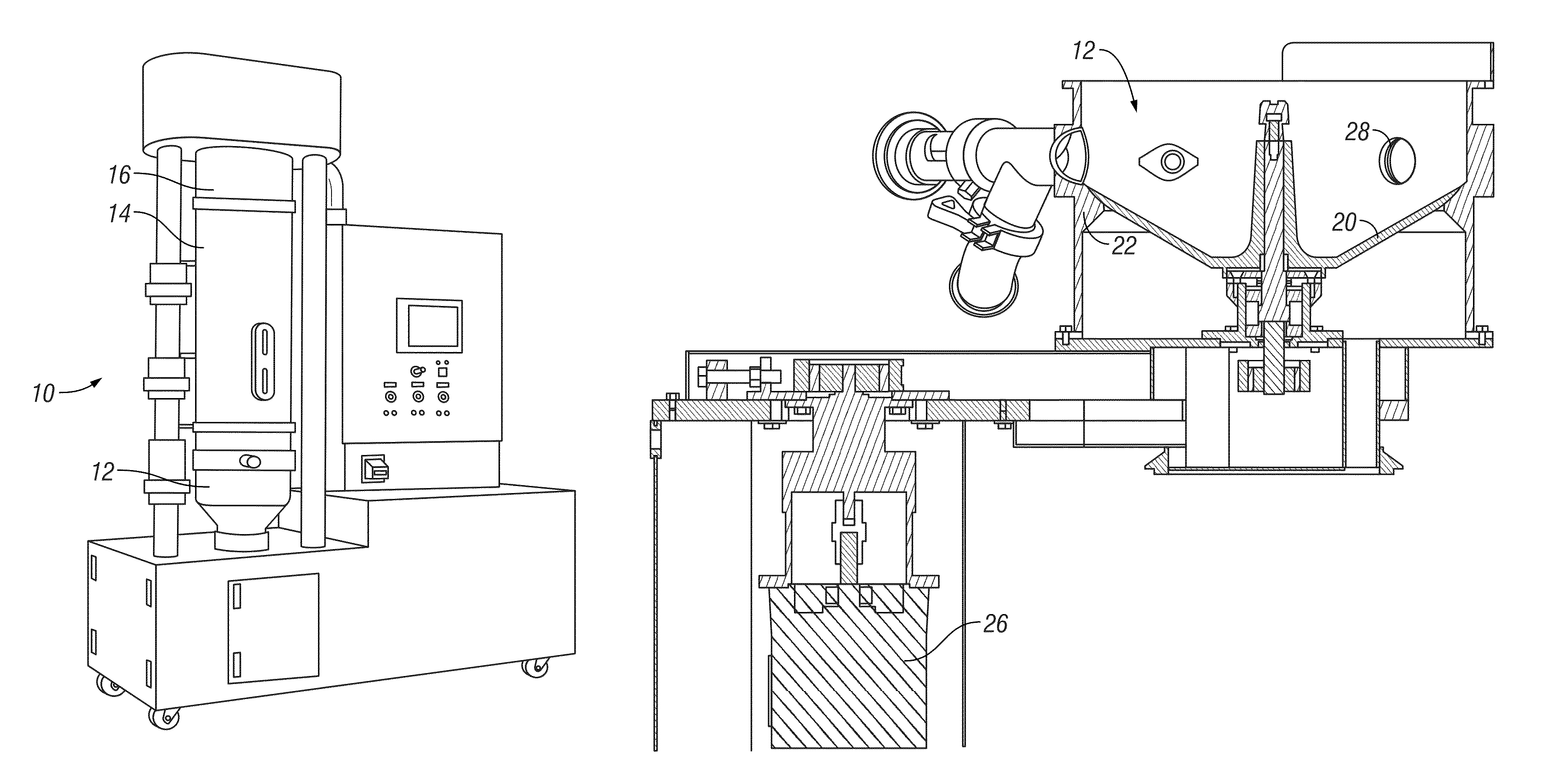
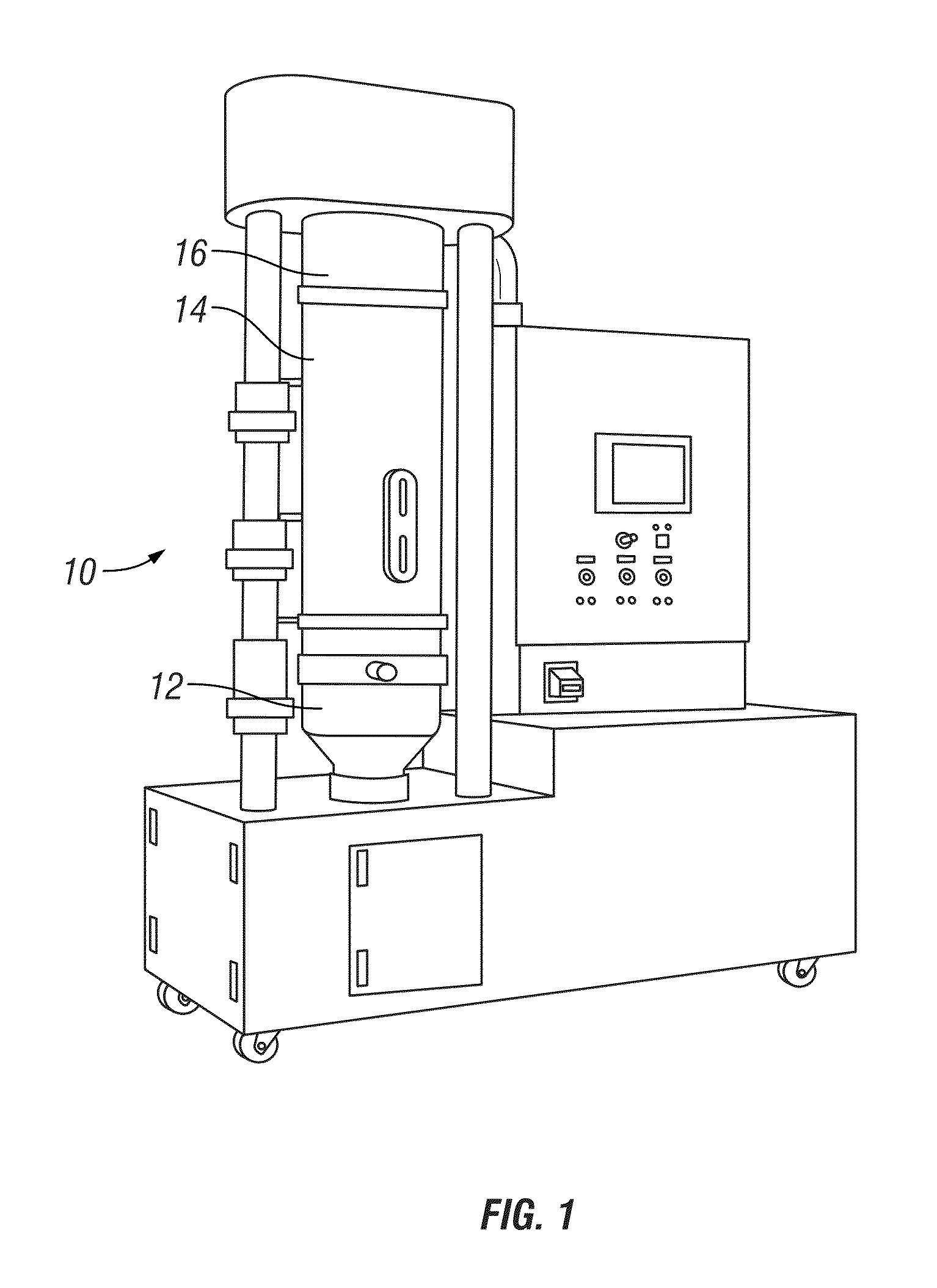
[0021]The rotor processor of the present invention is generally designated by the reference numeral 10 in the drawings. The processor includes a lower portion defining a rotor chamber 12, a central portion defining an expansion chamber 14, and an upper portion 16 housing the pulse filter. The expansion chamber 14 and pulse chamber filter 16 are conventional.

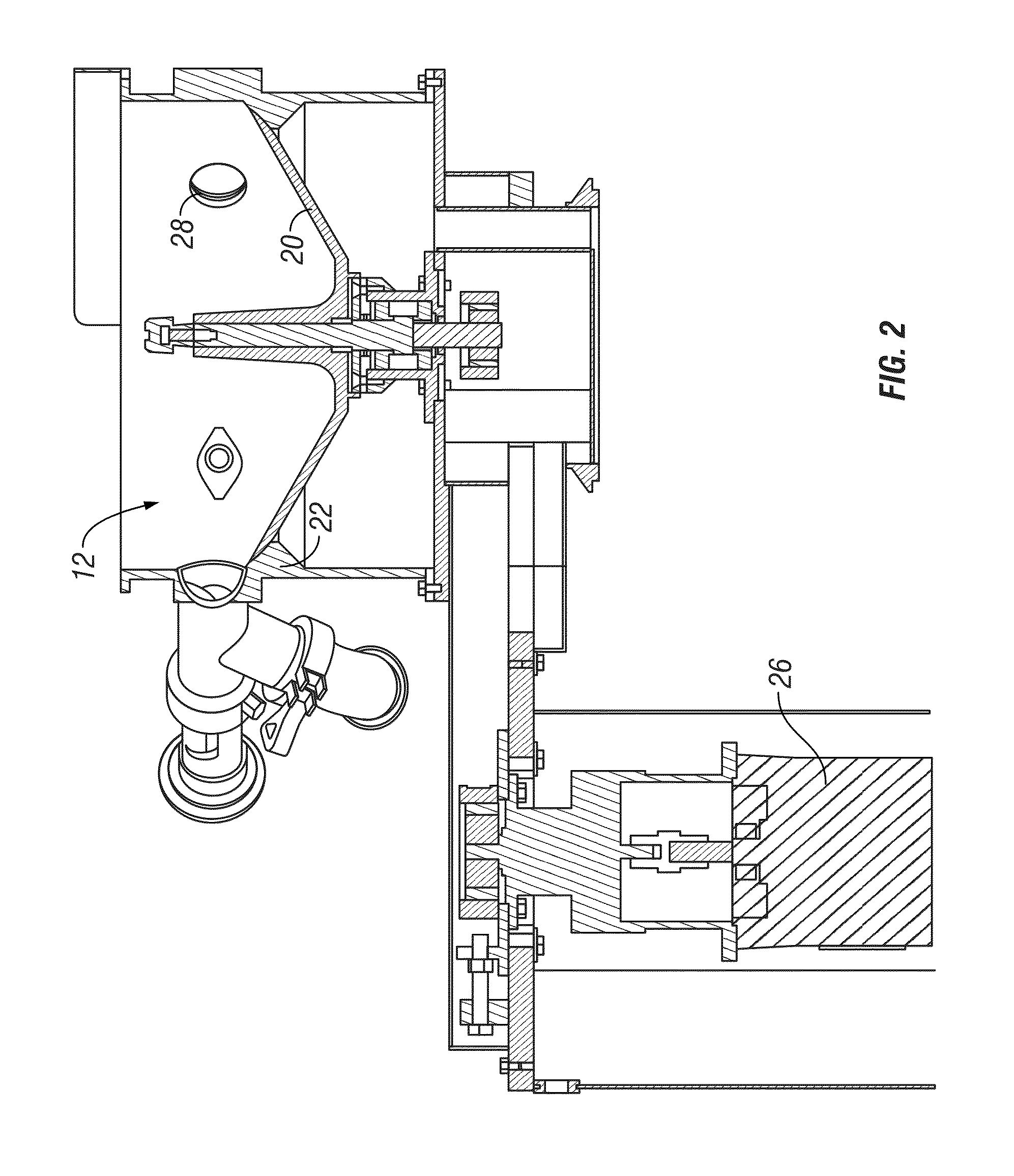
[0022]The present invention is directed towards the rotor chamber 12, which is defined by a substantially cylindrical stator 18 having a concave or dish-shaped rotor 20. The internal wall of the stator 18 has a ledge 22. The perimeter edge of the rotor 20 extends over the upper surface of the ledge 22, and when the rotor processor 10 is operating, the rotor 20 lifts off of the ledge 22 to define a small gap through which air flows upwardly. This gap structure and function is disclosed in Applicant's co-pending application Ser. No. 11 / 669,544 filed Jan. 31, 2007 and entitled ROTOR PROCESSOR.

[0023]The rotor 20 is mounted on a shaft...


PUM

PropertyMeasurementUnit
air pressureaaaaaaaaaa
sizeaaaaaaaaaa
weight gainaaaaaaaaaa

Abstract

The improved rotor processor of the present invention includes a stator with a rotatable rotor defining a rotor chamber in which particles are circulated for coating or layering. A spray gun mounted to the stator adjacent the rotor directs liquid into the rotor chamber, while a powder feed system mounted in the stator adjacent the rotor directs dry powder into the rotor chamber. The spray gun and powder feed system are spaced apart circumferentially so as to define a spray zone and a separate powder zone through which the circulating particles repeatedly and sequentially pass. The powder feed system includes a feed screw conveyor, an eductor, and a flexible conduit for delivering micronized powders, such as polymers or glidants, to the rotor chamber.

Description

CROSS-REFERENCE TO RELATED APPLICATIONS[0001]This application claims priority under 35 U.S.C. §119 of provisional application Ser. Nos. 61 / 087,083 filed Aug. 7, 2008 and 61 / 087,089 filed Aug. 7, 2008, which applications are hereby incorporated by reference in their entirety.FIELD OF THE INVENTION[0002]The invention is directed towards a rotor processor for coating or layering micronized particles with a polymer in a rotor processor. An improvement to the processor is directed to a powder feed system for introducing dry polymers and dry glidants into the rotor chamber and onto the circulating particles.BACKGROUND OF THE INVENTION[0003]Coating of small particulates, commonly known as cores, beads, crystals, pellets, granules or seeds, is well known for creating spherical particles, such as pharmaceuticals. The typical size for such particles is 50-10,000 microns. The coating material is normally a polymer, which may be a copolymer or monomer. A rotor processor is commonly used for suc...

Claims


Application Information

Patent Timeline
Patent Type & Authority Patents(United States)
IPC IPC(8): B05B17/00B01F13/10B01J2/00B01J2/14B01J2/16B01J8/38B01F33/40
CPCB01J2/006B01J2/14B01J2/16B01J8/386B01F2013/1094B01F33/8363
Inventor JENSEN, BRIAN, K.
Owner VECTOR CORP
Why Eureka
Try Eureka