Grounding bridge

a grounding bridge and connector technology, applied in the direction of electrical apparatus casings/cabinets/drawers, coupling device connections, casings/cabinets/drawers, etc., can solve the problems of limited and expensive commercial products which are capable of achieving the desired mounted connection, and components which are expensive to manufacture, so as to achieve high efficiency and rapid and easy threading. advanced

Active Publication Date: 2014-08-19
BRIDGEPORT FITTINGS LLC
View PDF30 Cites 9 Cited by
  • Summary
  • Abstract
  • Description
  • Claims
  • Application Information

AI Technical Summary

Benefits of technology

[0013]By employing the present invention, all of the difficulties and drawbacks of prior art systems have been eliminated and an efficient, easily manufactured and easily assembled bonding bar or grounding bridge is achieved. In accordance with the present invention, a single housing, component or element is constructed incorporating a plurality of passageways or receiving zones formed therein, with each passageway or receiving zone cooperatively associated with a locking screw or set screw configured to enable grounding conductors to be inserted through the passageway / receiving zone and securely mounted therein. In addition, the plurality of passageways / receiving zones are mounted in cooperating association with a mounting ring or clamp constructed for being quickly and easily secured to a clamp, conductor or conduit mounted to an electrical box, junction box, meter box, or similar enclosure.
[0015]In this way, all of the requirements for a highly effective intersystem bonding termination are realized and all of the newly enacted code provisions are satisfied. Furthermore, the present invention achieves a combination grounding rod bridge assembly which effectively provides the desired bonding of the electrical system in a building or house with the grounding conductors from telephones, cable television, satellite receivers, radios, television antennas, satellite dishes, and the like.
[0016]In the preferred construction, the grounding bar bridge of the present invention is constructed as a separate and independent housing or element which is affixed to the desired meter box, junction box, electrical outlet box and the like, while also incorporating a plurality of separate and independent passageways or receiving zones formed therein, with each passageway or receiving zone incorporating a separate set screw or locking screw threadedly mounted to the housing. In this regard, each locking screw or set screw is positioned for enabling a grounding conductor to be telescopically inserted into a passageway / receiving zone, with the set screw, locking screw being quickly and easily threadedly advanced for contacting and securing the grounding conductor to the grounding bar / grounding bridge assembly.
[0017]Although the grounding bar / grounding bridge assembly of the present invention may incorporate any desired number of passageways or receiving zones for enabling a wide variety of various communication systems to be mounted therewith, typically, the combination grounding rod bridge assembly incorporates between about four and six passageways or receiving zones. In this way, conventional installations of various communication systems can be easily accommodated in their entirety.

Problems solved by technology

Although these requirements have been in existence for several years, commercially available products which are capable of achieving the desired mounted connections are both limited and expensive.
Typically, these prior art products incorporate components which are expensive to manufacture due to tolerance requirements for enabling these components to be secured to the desired grounding rod / grounding electrode conductor.

Method used


Image

  • Grounding bridge
  • Grounding bridge
  • Grounding bridge

Examples


Embodiment Construction

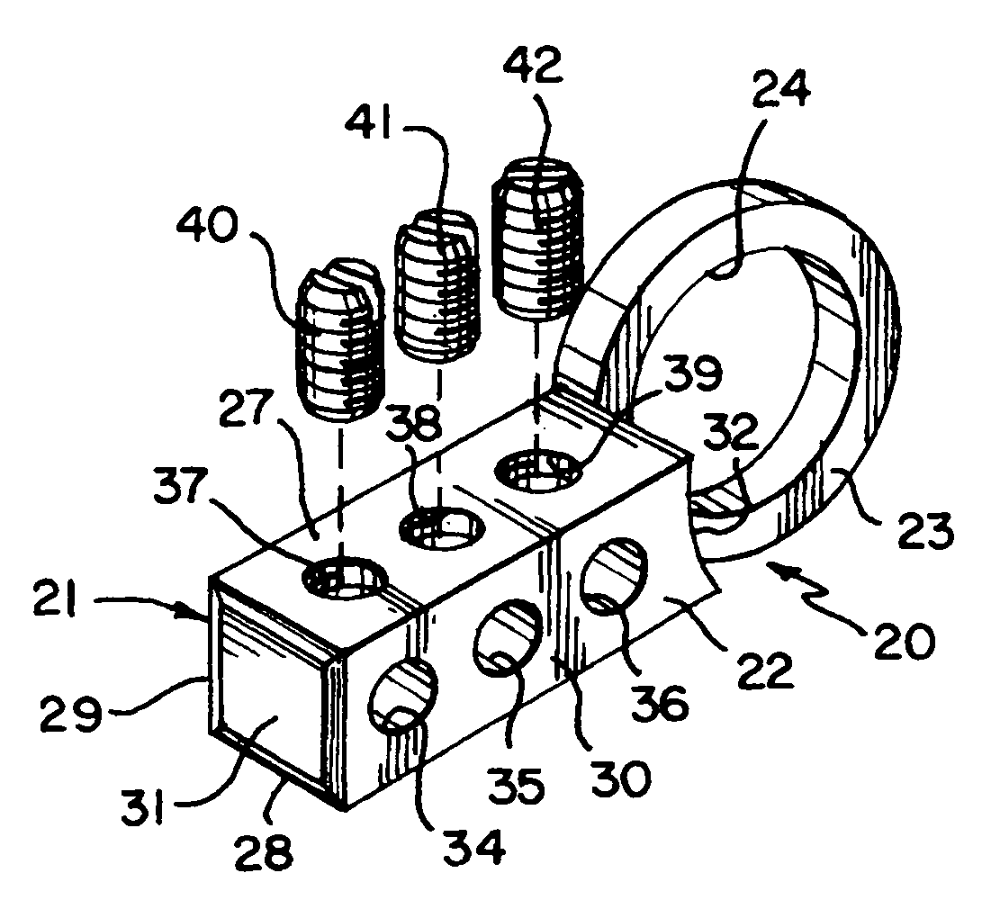
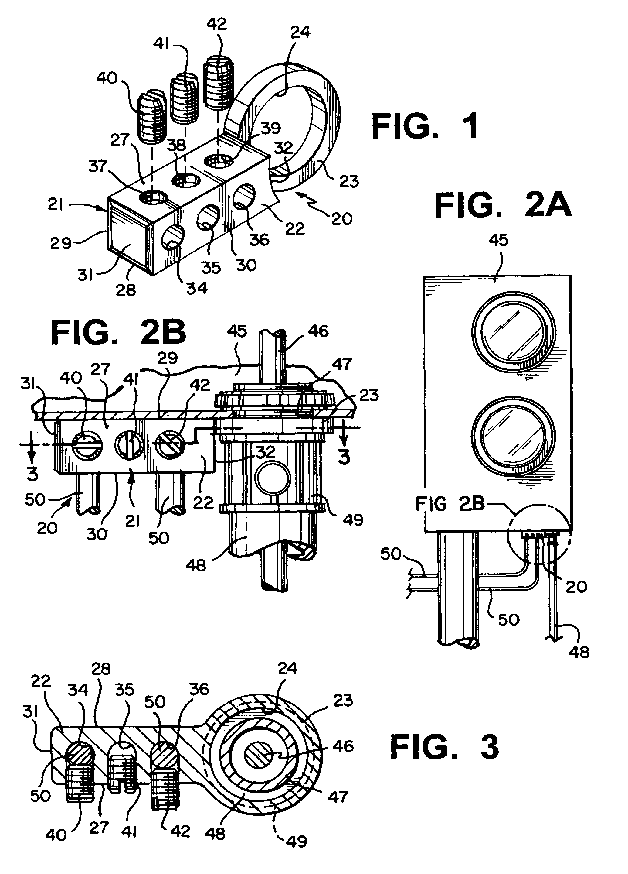
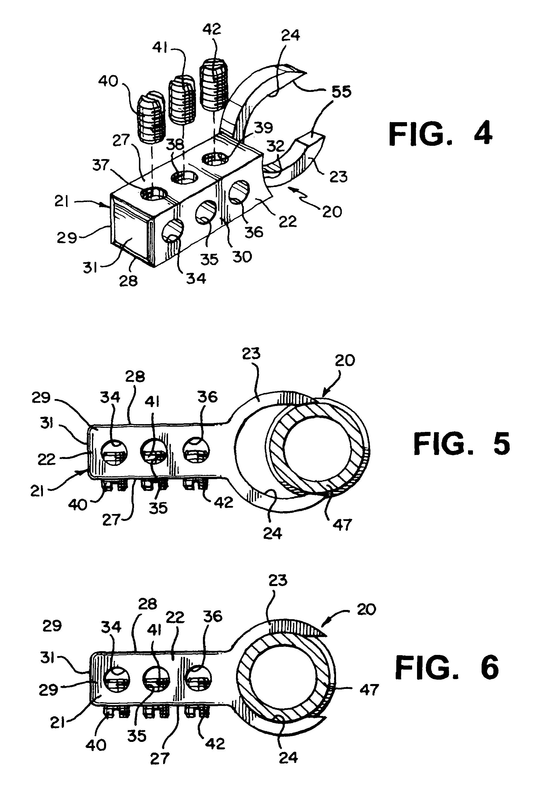
[0028]By referring to FIGS. 1-6, along with the following detailed discussion, the construction, operation, and installation of the grounding bridge assembly of the present invention can best be understood. In addition, in this disclosure, two alternate embodiments of the present invention are fully shown and described. However, further alternate embodiments of the present invention can be implemented without departing from the scope of this invention. Consequently, it should be understood that the following detailed description, as well as the drawings associated herewith, are provided for exemplary purposes and are not intended as a limitation of the present invention.

[0029]By referring to FIGS. 1-3, along with the following detailed discussion, the construction of one preferred embodiment of grounding bridge assembly 20 of the present invention can best be understood. As depicted, in this embodiment, grounding bridge assembly 20 comprises housing member 21 which incorporates gene...


PUM


Abstract

By providing a single housing, component or element incorporating a plurality of passageways or receiving zones formed therein in cooperating association with a mounting ring or clamp constructed for being quickly and easily secured to a clamp, conductor or conduit mounted to an electrical box, junction box, meter box, or similar enclosure, an efficient, easily manufactured and easily assembled bonding bar or grounding bridge is achieved. Preferably, the plurality of passageways / receiving zones are constructed with each passageway or receiving zone cooperatively associated with a locking screw or set screw configured to enable grounding conductors to be inserted through the passageway / receiving zone and securely mounted therein. In this way, grounding conductors from telephones, cable televisions, satellite receivers, radios, television antennas, and the like may be inserted into the passageways / receiving zones and securely mounted in the desired position.

Description

TECHNICAL FIELD[0001]This invention relates to electrical connectors, and more particularly, to electrical clamps or connectors constructed for bonding and grounding communication systems.BACKGROUND OF THE INVENTION[0002]In the field of wiring homes and buildings, whether for new construction or for improvements or expansion, substantial development and product improvements have been made. Typically, these improvements are directed to enabling installers to securely and safely mount any desired wiring to any desired location in the most efficient and quickest manner.[0003]In any particular installation or location, various conduits or cables must be interconnected to each other as well as connected to the primary power supply in a suitable power distributing outlet box, junction box, meter box, or other enclosure. In these instances, flexible metal conduit and / or armor or metalclad cables within which the electrical power carrying wires are contained, must be securely mounted to the...

Claims


Application Information

Patent Timeline
Patent Type & Authority Patents(United States)
IPC IPC(8): H05K5/02H01R4/34H01R4/36H01R4/64H01R4/66H01R11/09H01R13/648
CPCH01R4/64H01R4/34
Inventor KIELY, KENNETH, M.
Owner BRIDGEPORT FITTINGS LLC
Why Eureka
Try Eureka