Compact bandpass filter with no third order response

a bandpass filter and filter technology, applied in the field of microwave filter, can solve problems such as additional losses, and achieve the effect of low loss

Active Publication Date: 2014-08-19
VALENTINE RES
View PDF12 Cites 1 Cited by
  • Summary
  • Abstract
  • Description
  • Claims
  • Application Information

AI Technical Summary

Problems solved by technology

Such additional filtering requires the use of additional printed circuit board space, and the longer lengths traversed by the radio frequency signal causes additional losses.

Method used


Image

  • Compact bandpass filter with no third order response
  • Compact bandpass filter with no third order response
  • Compact bandpass filter with no third order response

Examples


Embodiment Construction

[0015]In the following detailed description of the illustrated embodiments, reference is made to the accompanying drawings that form a part hereof, and in which is shown by way of illustration, and not by way of limitation, specific embodiments in which the invention may be practiced. It is to be understood that other embodiments may be utilized and that changes may be made without departing from the spirit and scope of various embodiments of the present invention. The microwave filter of the present application is described with reference to microstrip technology for which it is initially being used.

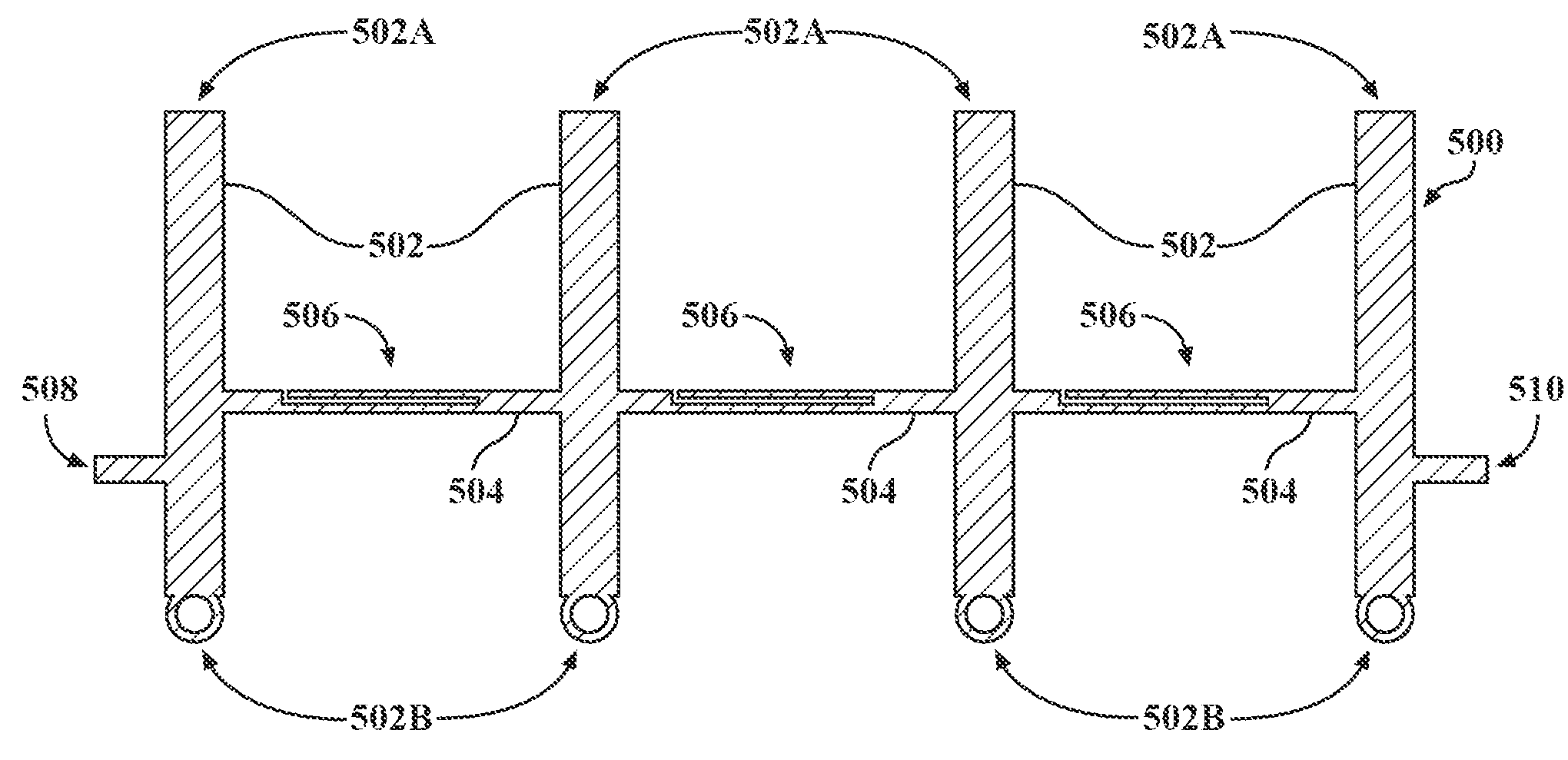
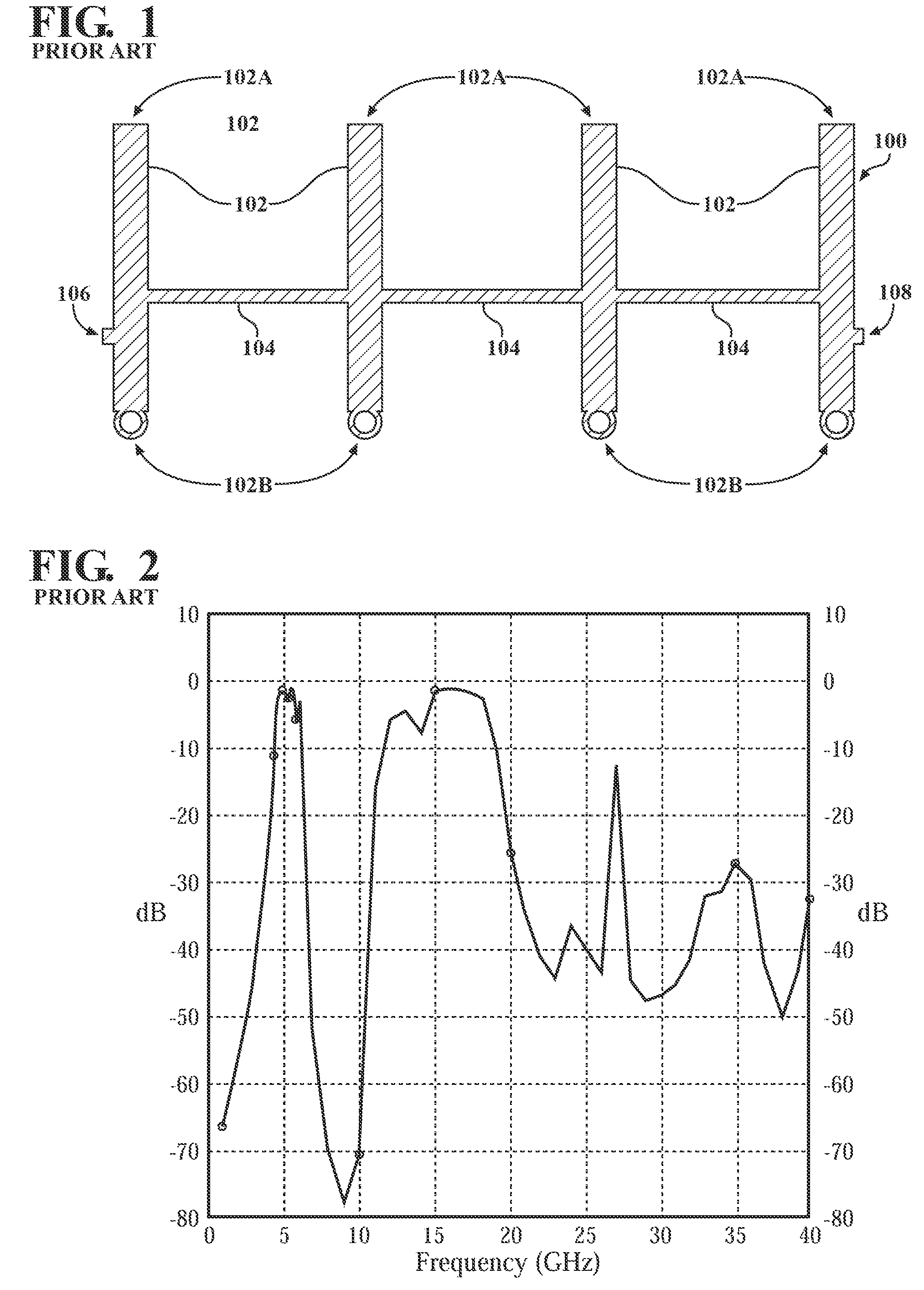
[0016]Reference is made to FIG. 1 which shows a conventional design for a microstrip bandpass filter 100 which comprises a plurality of vertical microstrip elements 102 placed parallel to one another and connected to one another by horizontal microstrip elements 104. The upper ends 102A of the elements 102 are open while the lower ends 102B of the elements 102 are connected to ground. F...


PUM


Abstract

A bandpass filter passes a range of frequencies with low loss while suppressing frequencies above and below the passed range of frequencies. One or more spurlines is included into the existing structure of the bandpass filter so that a selected odd multiple of the passed frequency range is suppressed.

Description

CROSS REFERENCE TO RELATED APPLICATIONS[0001]The present application is related to U.S. patent application Ser. No. 12 / 983,351 entitled MICROWAVE FILTER which was filed on Jan. 3, 2011, is assigned to the assignee of the present application and is incorporated by reference herein in its entirety. The present application is related to U.S. patent application Ser. No. 12 / 983,383 entitled METHODS AND APPARATUS FOR RECEIVING RADIO FREQUENCY SIGNALS, now U.S. Pat. No. 8,478,223, which was filed on Jan. 3, 2011, is assigned to the assignee of the present application and is incorporated by reference herein in its entirety.BACKGROUND OF THE INVENTION[0002]The present invention relates in general to microwave signal processing circuitry and, more particularly, to a microwave filter illustrated in a bandpass filter implemented in microstrip circuitry for which it is initially being used.[0003]Bandpass filters are designed to pass a desired range of frequencies and to reject others above and b...

Claims


Application Information

Patent Timeline
Patent Type & Authority Patents(United States)
IPC IPC(8): H01P1/203H01P7/08
CPCH01P1/20363H01P7/082H01P1/2039
Inventor NUSAIR, MARWAN, E.
Owner VALENTINE RES
Why Eureka
Try Eureka