Robot system having error detection function of robot and control method thereof

a robot and error detection technology, applied in the field of robot systems having robot errors, can solve the problems of inability to detect collisions with high accuracy

Active Publication Date: 2014-08-19
FANUC LTD
View PDF21 Cites 7 Cited by
  • Summary
  • Abstract
  • Description
  • Claims
  • Application Information

AI Technical Summary

Problems solved by technology

Even when the robot arm collides with a human or an object, for example, the collision, therefore, cannot be detected with high accuracy.

Method used


Image

  • Robot system having error detection function of robot and control method thereof
  • Robot system having error detection function of robot and control method thereof
  • Robot system having error detection function of robot and control method thereof

Examples


first embodiment

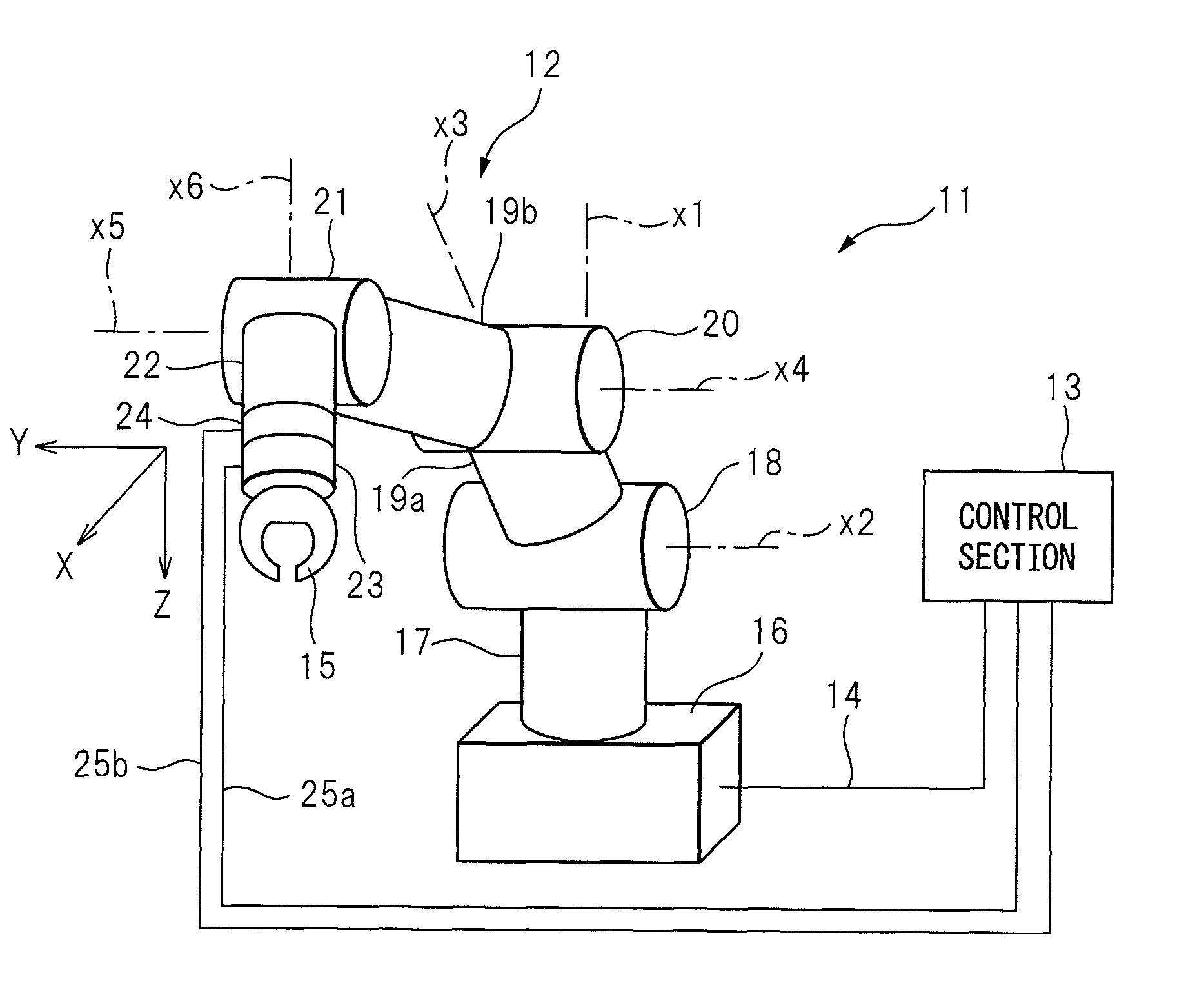
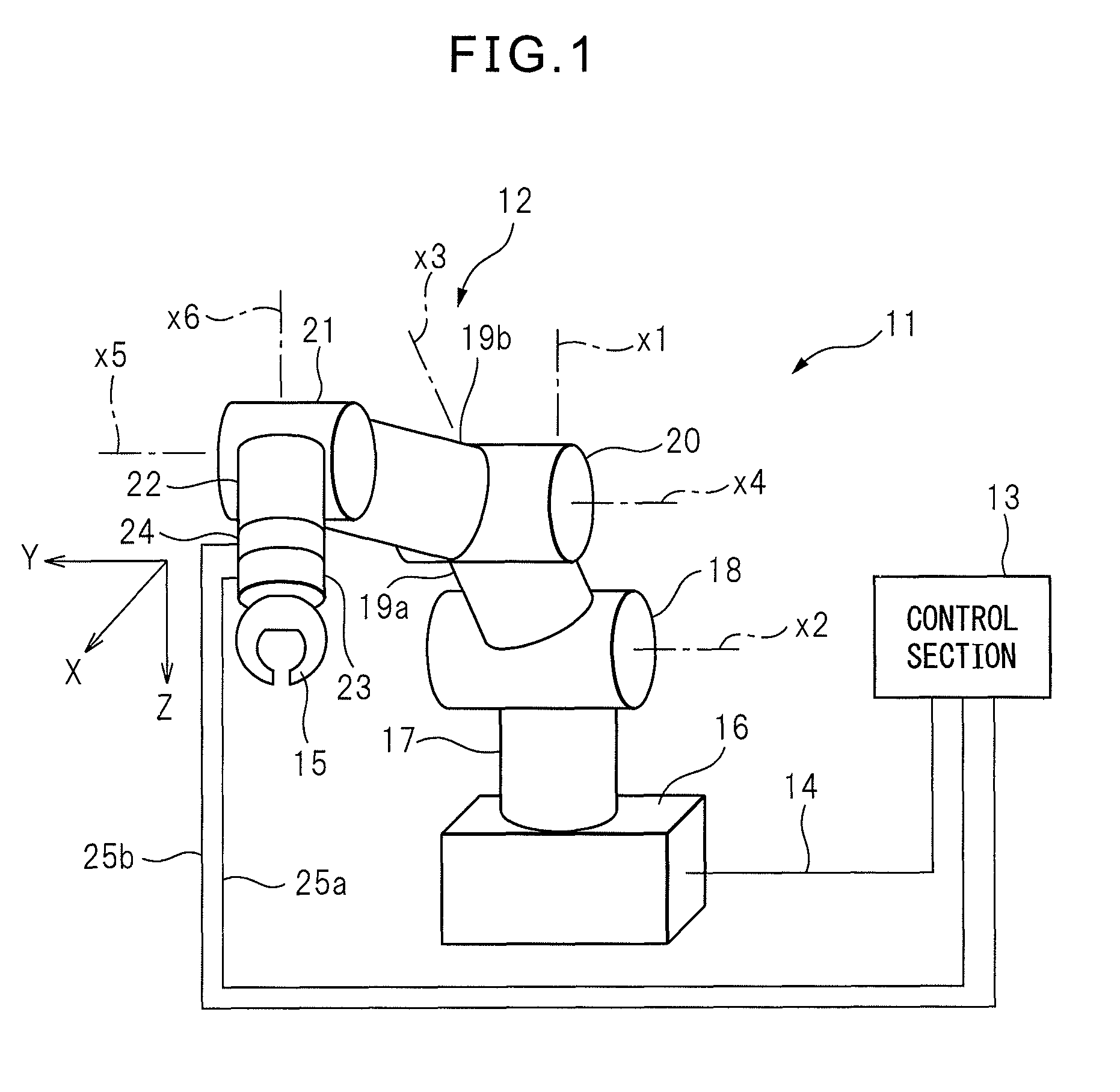
[0031]Hereinafter, an embodiment of the present invention will be described with reference to the accompanying drawings. FIG. 1 is a diagram schematically illustrating a structure of a robot system 11 according to the present invention. This robot system 11 comprises: an articulated robot 12 that constitutes, for example, a six-axis vertical articulated robot; and a control section 13 that is connected to articulated robot 12 to control operation of articulated robot 12. Articulated robot 12 and control section 13 are connected by a wiring 14. Articulated robot 12 comprises a working tool or a robot hand 15. Robot hand 15 can grasp, for example, a workpiece. This articulated robot 12 is disposed in a space where, for example, articulated robots 12 and people work together.

[0032]Articulated robot 12 comprises: a base stand 16 that is stably fixed, for example, to a floor surface; a proximal end arm 17 that is coupled to base stand 16 rotatably, for example, about a rotational axis li...

second embodiment

[0051]FIG. 6 is a diagram schematically illustrating a structure of a robot system 11a according to the present invention. In this figure, elements having construction or structure identical to those described above are designated by the same reference numerals. In this robot system 11a, first and second sensors 23 and 24 are connected to a second control section 27. The first and second detection values are output to second control section 27. Second control section 27 is connected to control section 13 described above via a wiring 28. Second control section 27 executes the error detection software as described above. However, control section 13 controls the operation of articulated robot 12 based on, for example, an alarm signal output from second control section 27. The process to detect the error and the process to control the operation of articulated robot 12 is performed by the separate control sections and, therefore, processing speed in robot system 11 can be increased.

third embodiment

[0052]FIG. 7 is a diagram schematically illustrating a structure of a robot system 11b according to the present invention. In this figure, elements having construction or structure identical to those described above are designated by the same reference numerals. In this robot system 11b, first and second sensors 23 and 24 adjacent to each other are disposed between base stand 16 and proximal end arm 17. First sensor 23 is attached to, for example, proximal end arm 17. Second sensor 24 is attached to, for example, base stand 16. These first and second sensors 23 and 24 can detect the forces acting on articulated robot 12 between proximal end arm 17 and robot hand 15. Collision with most of articulated robot 12 can, therefore, be detected with high accuracy. In addition, this robot system 11b can implement the effects similar to those described above.


PUM


Abstract

When an error occurs in robot system, a difference between first and second detection values of two sensors or first and second sensors occurs due to differences in position and responsibility. When this difference exceeds a predetermined threshold, control section detects that a difference has occurred in robot system. The first and second detection values of two sensors or first and second sensors are compared, and therefore, reliability of the detection values can be secured. Further, the abnormal state can be determined through the difference between the first and second detection values, and therefore, errors resulting from problems such as variations in gears and speed reducers due to temperature changes of the operational state and disposition environment of the robot can be avoided.

Description

RELATED APPLICATIONS[0001]The present application is based on, and claims priority from, Japanese Application Number 2011-084485, filed Apr. 6, 2011, the disclosure of which is hereby incorporated by reference herein in its entirety.BACKGROUND OF THE INVENTION[0002]1. Field of the Invention[0003]The present invention relates to a robot system having a robot and, in particular, it relates to a robot system having error detection function of a robot.[0004]2. Description of the Related Art[0005]Japanese Unexamined Patent Publication No. 2009-196030 discloses a robot controller that controls operation of a robot arm with high accuracy. In this robot controller, a sensor is incorporated into a driving section of axes of a robot arm. The robot arm is driven based on a command torque value output to this robot arm. The sensor outputs an actual detected torque value that is actually transferred to the robot arm. A computation section identifies a difference between the command torque value ...

Claims


Application Information

Patent Timeline
Patent Type & Authority Patents(United States)
IPC IPC(8): G05B19/04B25J9/16G05B19/418
CPCB25J9/1674
Inventor MORIOKA, MASAHIROADACHI, SATOSHI
Owner FANUC LTD
Why Eureka
Try Eureka