Syringe plunger driver system

a technology of syringe and driver, which is applied in the direction of suction devices, intravenous devices, other medical devices, etc., to achieve the effect of facilitating the loading of syringe plungers in relation to the plunger driver

Active Publication Date: 2014-08-26
CAREFUSION 303 INC
View PDF16 Cites 16 Cited by
  • Summary
  • Abstract
  • Description
  • Claims
  • Application Information

AI Technical Summary

Benefits of technology

The invention relates to a plunger driver system for syringes that can capture plungers of different sizes. The system has asymmetric arms that can be opened and closed to securely hold the plunger in place during operation. The system also includes a force detector to measure the force exerted by the plunger on a pushing surface. An alarm is triggered if the force exceeds a threshold. The system also has a force concentrator that helps to accurately detect the force exerted on the plunger. The technical effects of this invention are that it provides a reliable and efficient way to handle syringe plungers during injection procedures.

Problems solved by technology

Further, the control device comprises a rotation knob having a first rotation position at which it moves the first and second arms outwardly into the syringe plunger non-engagement position in opposition to the first bias device, and a second rotation position at which the rotation knob does not prevent the first and second arms from capturing the syringe plunger flange.

Method used


Image

  • Syringe plunger driver system
  • Syringe plunger driver system
  • Syringe plunger driver system

Examples


Embodiment Construction

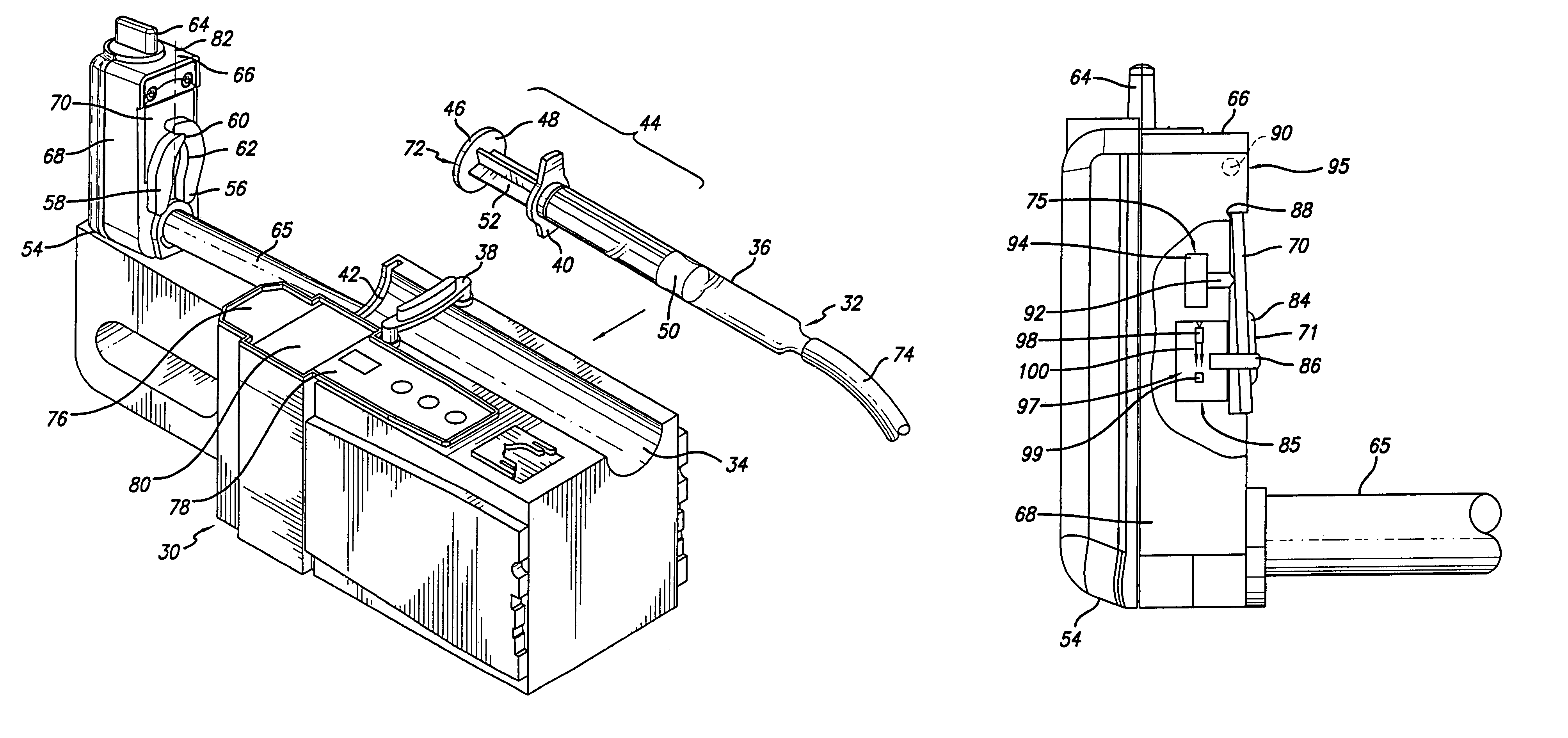
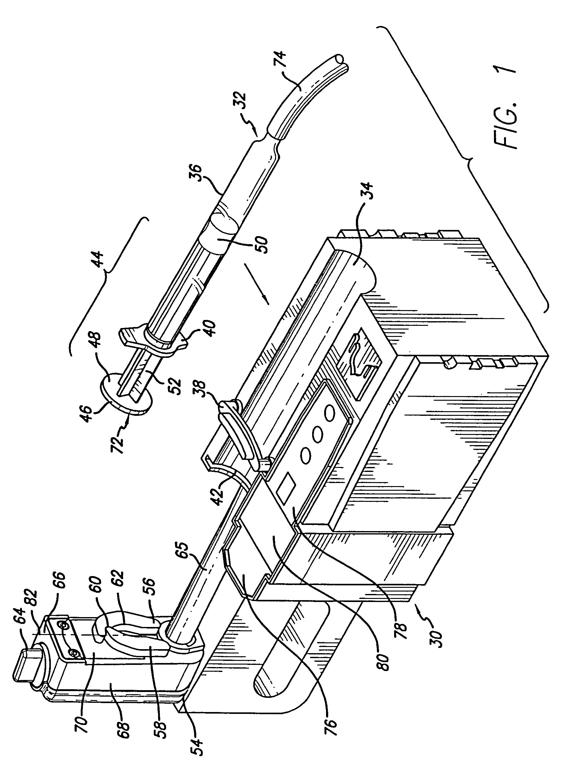
[0029]Referring now to the drawings with more particularity, wherein like reference numerals designate like or corresponding elements among the several views, there is shown in FIG. 1 a perspective view of a syringe pump 30 having a syringe plunger driver system in accordance with the principles of the invention. A syringe 32 is shown next to the pump rather than mounted in the pump, for clarity of illustration, with an arrow indicating the mounting location. The syringe pump 30 includes a syringe cradle 34 in which the syringe barrel 36 will rest when properly mounted in the pump. The cradle 34 includes a syringe barrel clamp 38 to securely hold the syringe barrel 36 in a fixed position in the cradle 34 so that lateral movement is resisted. The syringe barrel clamp 38 is pivoted in this embodiment so that it may be moved into an open position to permit loading or removal of a syringe and a closed position in which it extends over the cradle 34 to hold a mounted syringe barrel 36. F...


PUM


Abstract

A syringe plunger driver system capable of capturing syringes of widely varying sizes comprises a pair of asymmetric plunger retainer arms pivotally mounted to a plunger driver. The system includes a low profile driver having a length that exceeds its width so that it may be mounted adjacent control modules and other operational modules. The arms are biased toward each other and one arm is longer than the other with a notch on an inside edge to receive the tip of the shorter arm when capturing small syringe flanges. A rotation knob mounted to the front surface of the low profile driver forces the arms apart when rotated to a first rotation position. A force sensor is mounted in the driver to detect occlusions in the fluid line. A processor monitors the force sensed by the force sensor and provides an alarm if the force exceeds a threshold. The driver includes a force concentrator that defines a pushing surface adapted to press against a plunger flange so that the force applied to the plunger flange is concentrated at a defined location for more accurate measurement.

Description

[0001]This application is a divisional of application Ser. No. 10 / 164,112, filed Jun. 5, 2002, now U.S. Pat. No. 7,150,724, the entire contents of which is incorporated herein by reference.BACKGROUND[0002]The invention is related generally to drive mechanisms for medical infusion pumps, and more particularly, to a system and method for driving the plunger of a syringe in a syringe pump.[0003]The infusion of medical fluids, such as parenteral fluids, into the human body is accomplished in many cases by means of a syringe pump in which a syringe containing the parenteral fluid is mounted. Syringe pumps typically secure the syringe barrel in a fixed position and push or “drive” the syringe plunger into the barrel at a controlled rate to expel the parenteral fluid. A fluid administration set conducts the expelled parenteral fluid from the syringe barrel to the patient. Many syringe pumps have an elongated lead screw rotated by a motor and a screw drive mechanism such as a split nut that...

Claims


Application Information

Patent Timeline
Patent Type & Authority Patents(United States)
IPC IPC(8): A61M1/00A61M5/145
CPCY10T29/49826Y10T29/49776A61M2202/0007A61M5/1452A61M2205/18Y10T29/49771A61M5/1456A61M5/1458Y10T29/49769
Inventor MORRIS, MATTHEW G.SCHWARTZ, DONALD F.
Owner CAREFUSION 303 INC
Why Eureka
Try Eureka