Continuity testing device

a testing device and continuous technology, applied in the direction of coupling device details, coupling device connections, instruments, etc., can solve the problem of reliably detection of incomplete fitting of retainers, and achieve the effect of reducing the cost of continuity testing devices

Active Publication Date: 2014-08-26
YAZAKI CORP
View PDF13 Cites 7 Cited by
  • Summary
  • Abstract
  • Description
  • Claims
  • Application Information

AI Technical Summary

Benefits of technology

[0011]An object of the present invention is thus to solve the above-described problems by providing a continuity testing device which allows the connector with the retainer fitted at the recess of the connector to be inserted smoothly into the connector insertion part along the transverse direction, which can perform reliable detection of the incomplete-fitting of the retainer, which can prevent the damage to the retainer when detecting the incomplete-fitting of the retainer and which can reduce the cost of the continuity testing device.
[0017]Consequently, since the upward movement of the continuity testing part is converted into the downward movement of the detection plate using the push pin and the lever, the detection plate can be moved downward easily and reliably, and the incomplete-fitting of the retainer can be detected with high accuracy.
[0019]According to the third aspect of the present invention described above, the push pin pushes up an one end of the lever to rotate the lever, and the other end of the rotated lever compresses the weak spring provided above the detection plate to move the detection plate downward. When the detection plate is contacted with the incompletely fitted retainer, the stiff spring provided below the detection plate is compressed slightly, so the stiff spring pushes back the detection plate, preventing the detection plate from being moved further in the downward direction. As a result, the retainer can be prevented from being deformed or damaged by the detection plate.
[0021]According to the fourth aspect of the present invention described above, since the case, the upper cover plate and an air cylinder used in the continuity testing device can be utilized in common in the another continuity testing device for the connector inserted in the vertical direction, the cost of the continuity testing device can be reduced.

Problems solved by technology

Furthermore, incomplete-fitting of the retainer can be detected reliably by the detection plate activated in conjunction with the continuity testing part, without relying on the manual detection by the worker.

Method used


Image

  • Continuity testing device
  • Continuity testing device
  • Continuity testing device

Examples


Embodiment Construction

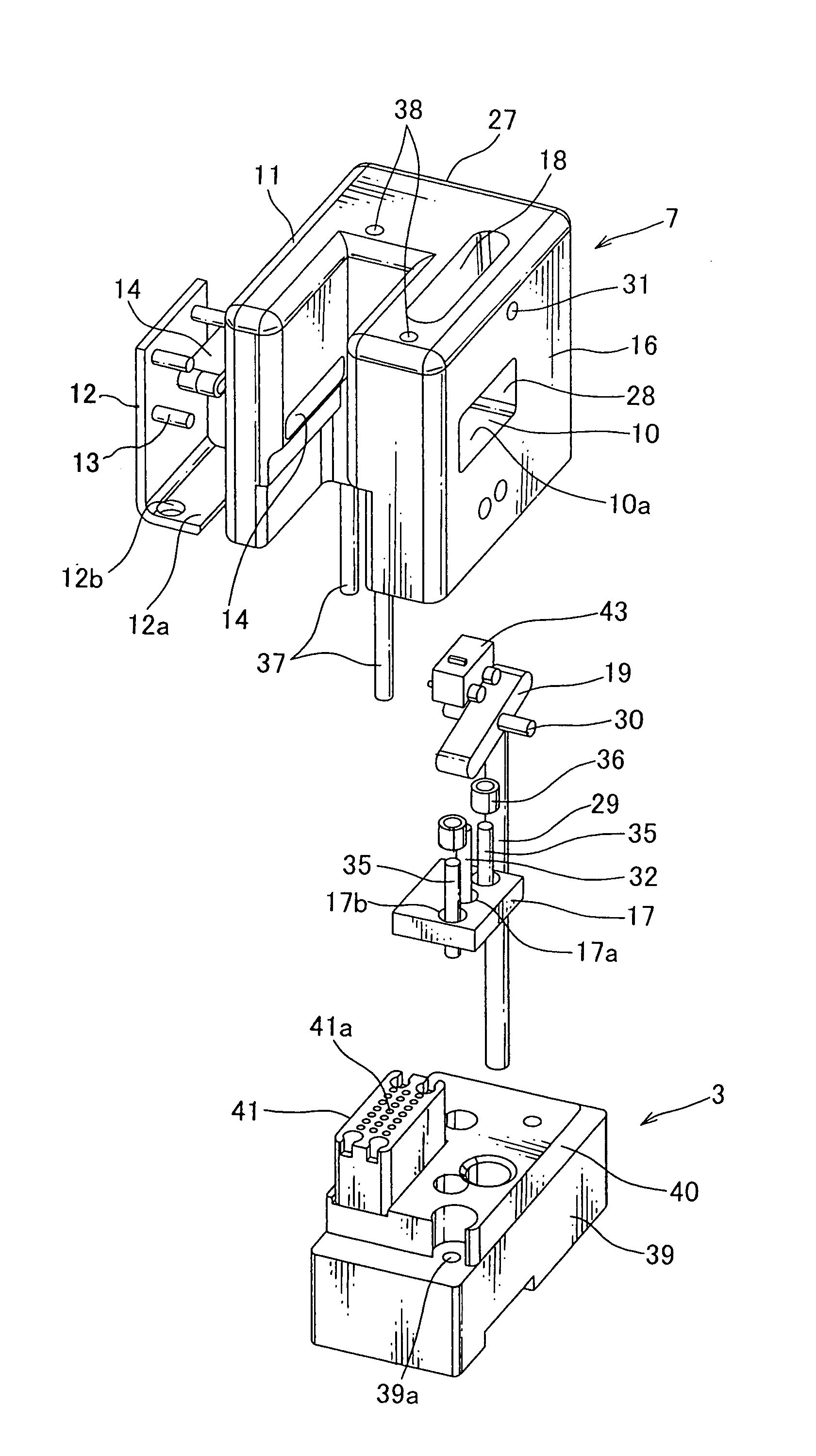
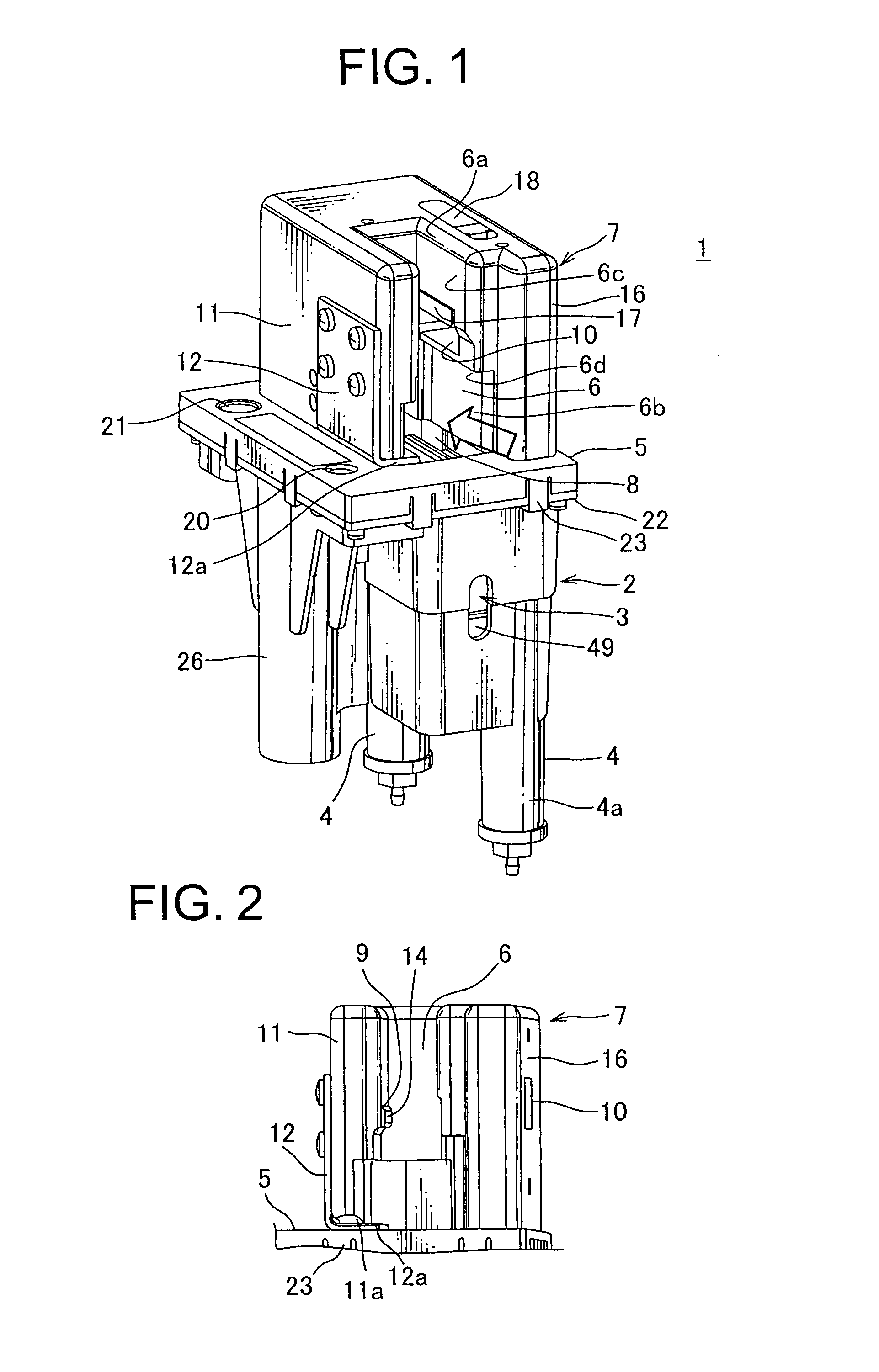
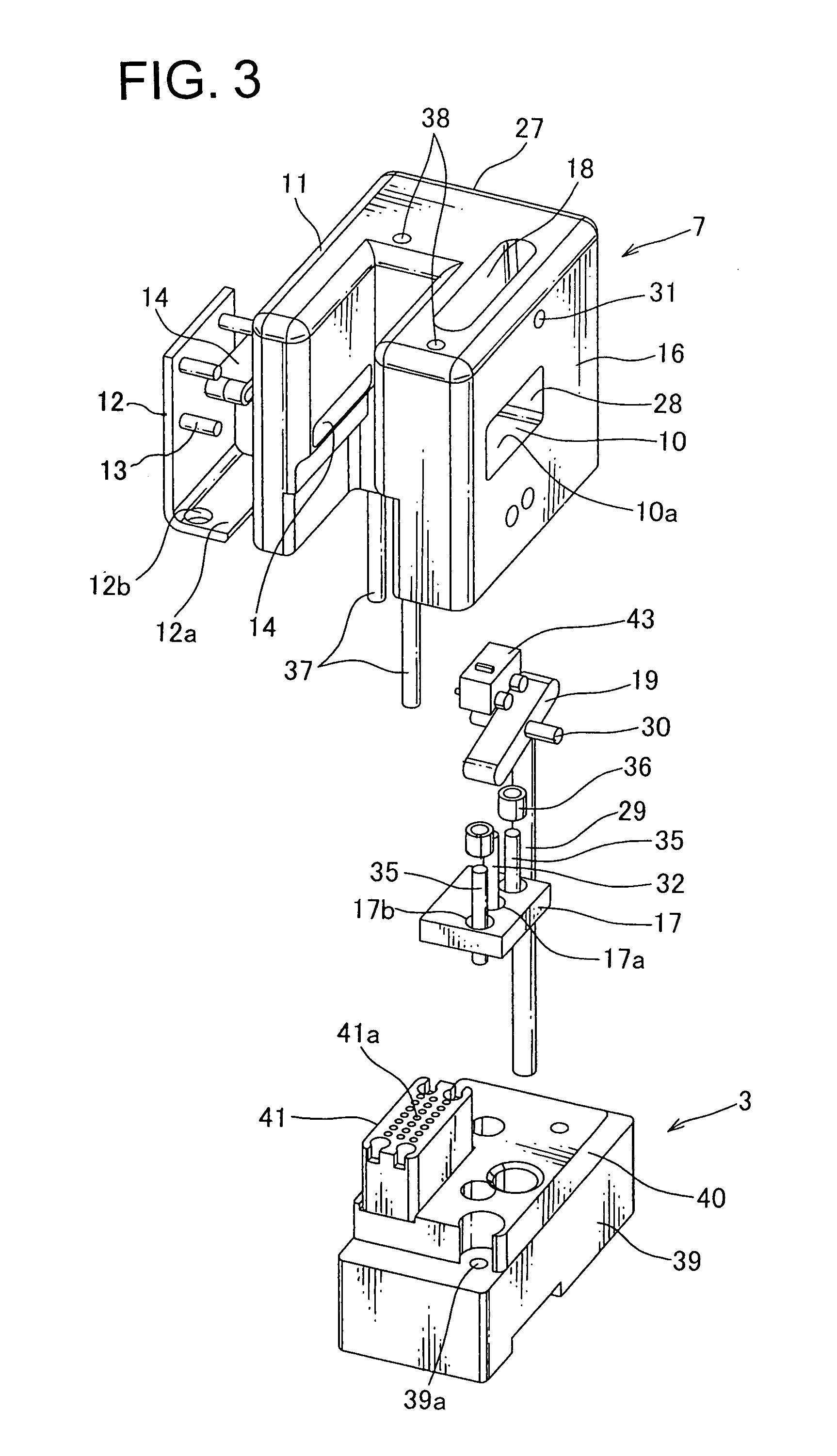
[0033]One embodiment of a continuity testing device according to the present invention is described below in reference with FIGS. 1 through 8.

[0034]Referring to FIG. 1, a continuity testing device 1 according to the present invention includes a case 2 made of synthetic resin or metal, a continuity testing part 3 arranged inside the case 2, a vertical air cylinder 4 arranged to move the continuity testing part 3 up and down in the vertical direction, an upper cover plate 5 provided on the case 2 and a connector guide block 7 made of synthetic resin and threadably mounted on the upper cover plate 5. The connector guide block 7 includes therein a connector insertion part 6. In the description, the vertical direction corresponds to the longitudinal direction of the continuity testing device, the transverse or the horizontal direction corresponds to a direction perpendicular to the vertical direction.

[0035]The cover plate 5 is provided with a rectangular opening 8 penetrating through the...


PUM


Abstract

A continuity testing device is provided which can reliably detect incomplete-fitting of the retainer of the connector. The continuity testing device includes a connector guide block into which the connector is inserted in a transverse direction and which is fixed above an opening formed on a cover plate of a case of the continuity testing device, a detection plate provided to the connector guide block and arranged above the connector so as to contact with the incompletely-fitted retainer of the connector when moved downward, a detection pin arranged at the detection plate, a continuity testing part arranged to move in the vertical direction toward the connector, a drive mechanism that operates the detection plate to move in the vertical direction in conjunction with the continuity testing part, and a switch that is activated by the detection pin when the detection pin is completely moved down to the switch.

Description

CROSS REFERENCE TO RELATED APPLICATION[0001]The priority application Japanese Patent Application No. 2010-162573 upon which this patent application is based is hereby incorporated by reference.BACKGROUND OF THE INVENTION[0002]1. Field of the Invention[0003]The present invention relates generally to a continuity testing device. More specifically, the present invention is directed to a continuity testing device having a mechanism for detecting incomplete-fitting of a retainer of a connector.[0004]2. Description of the Related Art[0005]In a conventional continuity testing device used to test an electrical continuity of a connector of a wire harness, the connector is typically inserted into the continuity testing device along a vertical direction downward from an upward position, or along a horizontal direction from the front into the back of the continuity testing device.[0006]One such continuity testing device is disclosed in Japanese Patent Application Publication No. 2007-85926 (her...

Claims


Application Information

Patent Timeline
Patent Type & Authority Patents(United States)
IPC IPC(8): G01R31/04
CPCH01R43/20G01R31/045H01R13/4361H01R2201/20G01R31/69
Inventor KOGASUMI, KOZO
Owner YAZAKI CORP
Why Eureka
Try Eureka