Communication system having a can bus and a method for operating such a communication system

a communication system and can bus technology, applied in the field of communication system having, can solve the problems of increasing the transmission rate of can buses, affecting the transmission speed of can buses,

Active Publication Date: 2014-08-26
ROBERT BOSCH GMBH
View PDF13 Cites 9 Cited by
  • Summary
  • Abstract
  • Description
  • Claims
  • Application Information

AI Technical Summary

Benefits of technology

[0004]A communication system according to an example embodiment of the present invention and an example method according to the present invention for operating the communication system may each have an advantage that the devices, which are interconnected via the CAN bus, are suitable for transmitting CAN data frames over the CAN bus in a first operating mode and for transmitting ASC (asynchronous serial communication) data frames in a second operating mode.
[0005]An advantage of the example embodiment of the present invention is that the ASC data frames are transmissible at a higher bus clock rate over the CAN bus in comparison with the CAN data frames. Furthermore, the ASC data frames have a much smaller header portion and thus a much larger useful data portion in comparison with CAN data frames. Thus, in an ASC data transmission, a very high useful data transmission rate is achievable because the protocol overhead is particularly small. In particular, the protocol overhead may be reduced from approximately 55% with CAN data frames to approximately 10%.
[0009]This prevents ASC data frames, which have been properly transmitted in the ASC time slot, from being destroyed by the device to be powered up only because the device does not yet have any knowledge of the time slot in which ASC data frames are transmitted and it interprets the ASC data frames incorrectly as faulty CAN data frames. The device is able to receive knowledge of when, i.e., in which time slot, ASC data frames are transmitted, only when it has synchronized itself to the time base of the communication system. Furthermore, an error counter of the device is frozen for the duration of the third operating mode, i.e., it is not incremented. This may be true of the transmit (Tx) error counter as well as the received (Rx) error counter. This prevents ASC data frames transmitted in the ASC time slot from resulting in a rapid incrementation of the error counter and the device being switched to an “error_passive” state (error level 128 exceeded: device does not transmit any error frames, forced pause before renewed transmission of messages) and / or a “bus_off” state (error level 256 exceeded: device is not allowed to send) before the device is synchronized to the time base of the communication system. In other words, in the third operating state, the device is able to recognize presumably faulty data, i.e., data not conforming to the CAN protocol, but this does not result in incrementation of the error counter and / or destruction of the presumably defective data frames.

Problems solved by technology

Among other things, this is due to the protocol overhead of the physical protocol required by the CAN bus, i.e., the header part of CAN messages may be larger than the useful data part or payload part of the message.
The ratio may be worsened by stuff bits.
In addition, the maximum feasible transmission rate of a CAN bus at the present time is limited to approximately 1 Mbit / sec (106 bits per second) due to physical boundary conditions and in particular due to delays on the CAN bus.
At a higher transmission rate, problems may occur in CAN bit arbitration which prevents collisions among messages, because the signal transit times between the most widely spaced nodes may exceed a bit time.
Furthermore, a high transmission rate results in steeper flanks of the transmitted signal, which in turn results in higher radiant emittance and thus poorer EMC properties of the communication system.
This prevents ASC data frames, which have been properly transmitted in the ASC time slot, from being destroyed by the device to be powered up only because the device does not yet have any knowledge of the time slot in which ASC data frames are transmitted and it interprets the ASC data frames incorrectly as faulty CAN data frames.
Furthermore, an error counter of the device is frozen for the duration of the third operating mode, i.e., it is not incremented.

Method used


Image

  • Communication system having a can bus and a method for operating such a communication system
  • Communication system having a can bus and a method for operating such a communication system
  • Communication system having a can bus and a method for operating such a communication system

Examples


Embodiment Construction

[0032]The same reference numerals in the figures denote the same components or those having the same function.

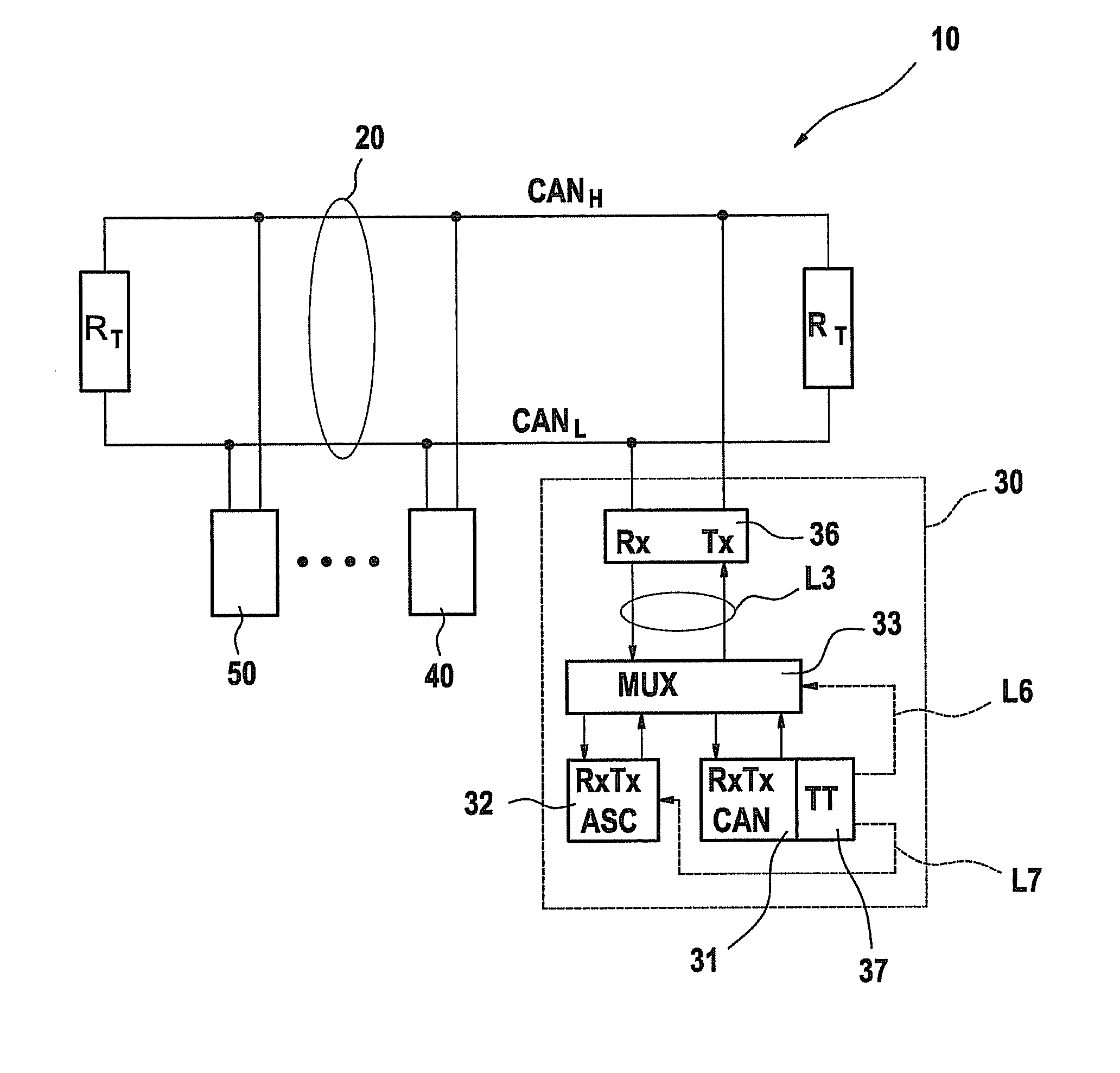
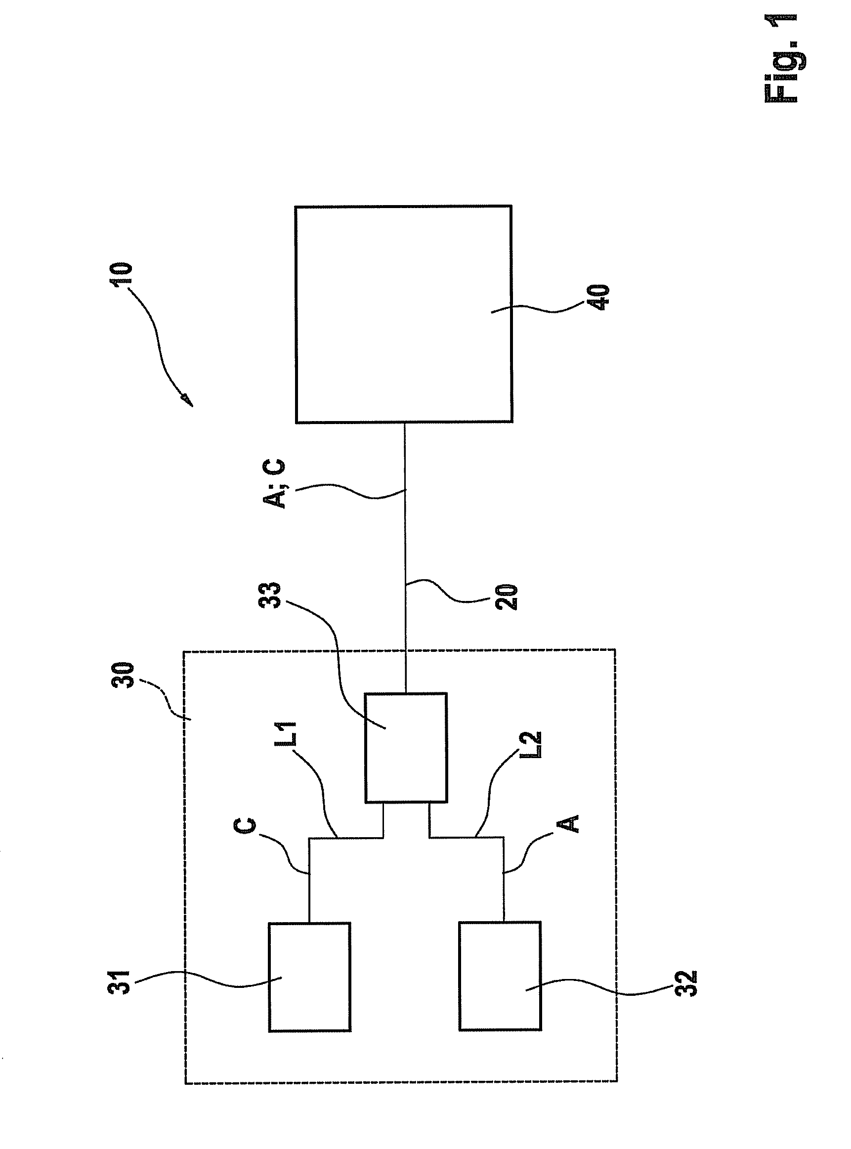
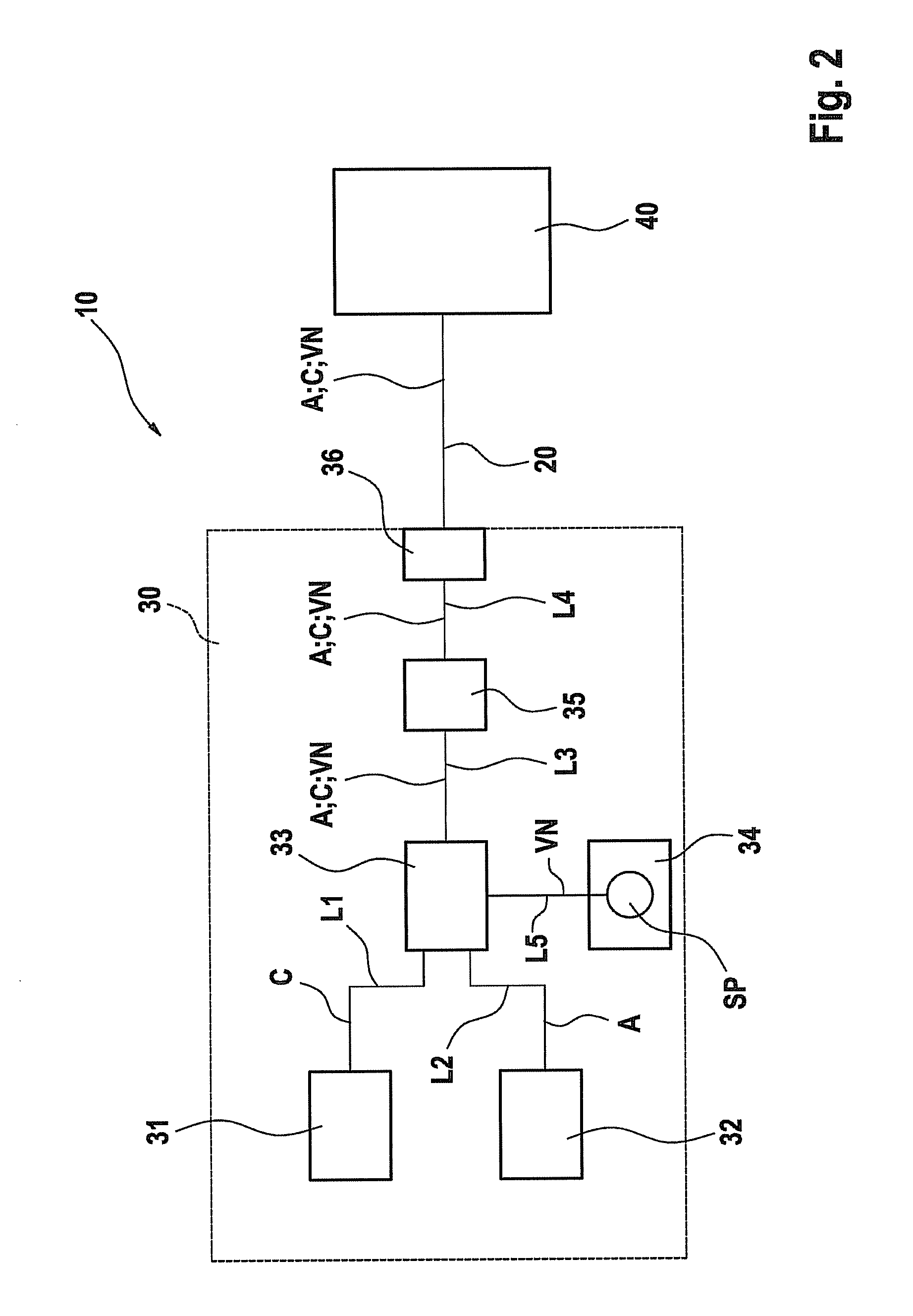
[0033]FIG. 1 shows an example communication system according to the present invention labeled with reference numeral 10 in its entirety. Communication system 10 includes a CAN bus 20, at least two devices 30, 40 (so-called nodes) linked by CAN bus 20 and a switch 33.

[0034]The at least two devices 30, 40 linked by CAN bus 20 include, for example, either one test device and at least one control unit or at least two control units. The test device is preferably provided in a workshop. The control devices are preferably provided in a motor vehicle. The present invention may of course also be used in other fields outside of a motor vehicle, for example, in aircraft, space vehicles, or machine tools.

[0035]In FIGS. 1 and 2, reference numerals 30 and 40, for example, denote two control units, which are designed to be identical. For reasons of simplicity, only first control unit 30 is...


PUM


Abstract

A communication system having one CAN bus and at least two devices interconnected by the CAN bus is described, at least one of the devices including: i) a CAN controller, which is suitable for transmitting CAN data frames over the CAN bus using a first physical protocol in a first operating mode; ii) an asynchronous serial communication interface unit, which is suitable for transmitting ASC data frames over the CAN bus using a second physical protocol in a second operating mode; iii) a first switching means, which is suitable for switching the first operating mode and the second operating mode depending on at least one agreement in effect between the device and at least one of the other devices; and iv) another switching means, which is suitable for switching the device to a third (restricted) operating mode, which differs from the first operating mode and the second operating mode, for powering up the device.

Description

FIELD OF THE INVENTION[0001]The present invention relates to a communication system having a CAN (controller area network) bus and a method for operating such a communication system.BACKGROUND INFORMATION[0002]In transmission of data over a CAN bus, the maximum capacity utilization of the bus in practice is usually approximately 50%. Among other things, this is due to the protocol overhead of the physical protocol required by the CAN bus, i.e., the header part of CAN messages may be larger than the useful data part or payload part of the message. For example, if the DLC (data length code) is 8, then 64 payload bits and 1+12+6+16+2+7=44 header bits are provided. The ratio may be worsened by stuff bits.[0003]In addition, the maximum feasible transmission rate of a CAN bus at the present time is limited to approximately 1 Mbit / sec (106 bits per second) due to physical boundary conditions and in particular due to delays on the CAN bus. This corresponds to a minimum bit time of 1 μsec (1...

Claims


Application Information

Patent Timeline
Patent Type & Authority Patents(United States)
IPC IPC(8): G06F13/36G06F13/40
CPCG06F13/4027H04L12/413
Inventor HARTWICH, FLORIAN
Owner ROBERT BOSCH GMBH
Why Eureka
Try Eureka