Position-measuring device

a technology of measuring device and position, applied in the direction of measurement device, instrument, computing, etc., can solve problems such as faulty binary information generation, and achieve the effect of improving dependability or operational reliability

Active Publication Date: 2014-09-02
DR JOHANNES HEIDENHAIN GMBH
View PDF10 Cites 3 Cited by
  • Summary
  • Abstract
  • Description
  • Claims
  • Application Information

AI Technical Summary

Benefits of technology

[0009]Example embodiments of the present invention provide improvements to the dependability or operational reliability of an absolute position-measuring device.

Problems solved by technology

This comparison with a definitively specified trigger threshold has the disadvantage that fluctuations in the analog scanning signals may result in a faulty generation of the binary information.

Method used


Image

  • Position-measuring device
  • Position-measuring device
  • Position-measuring device

Examples


Embodiment Construction

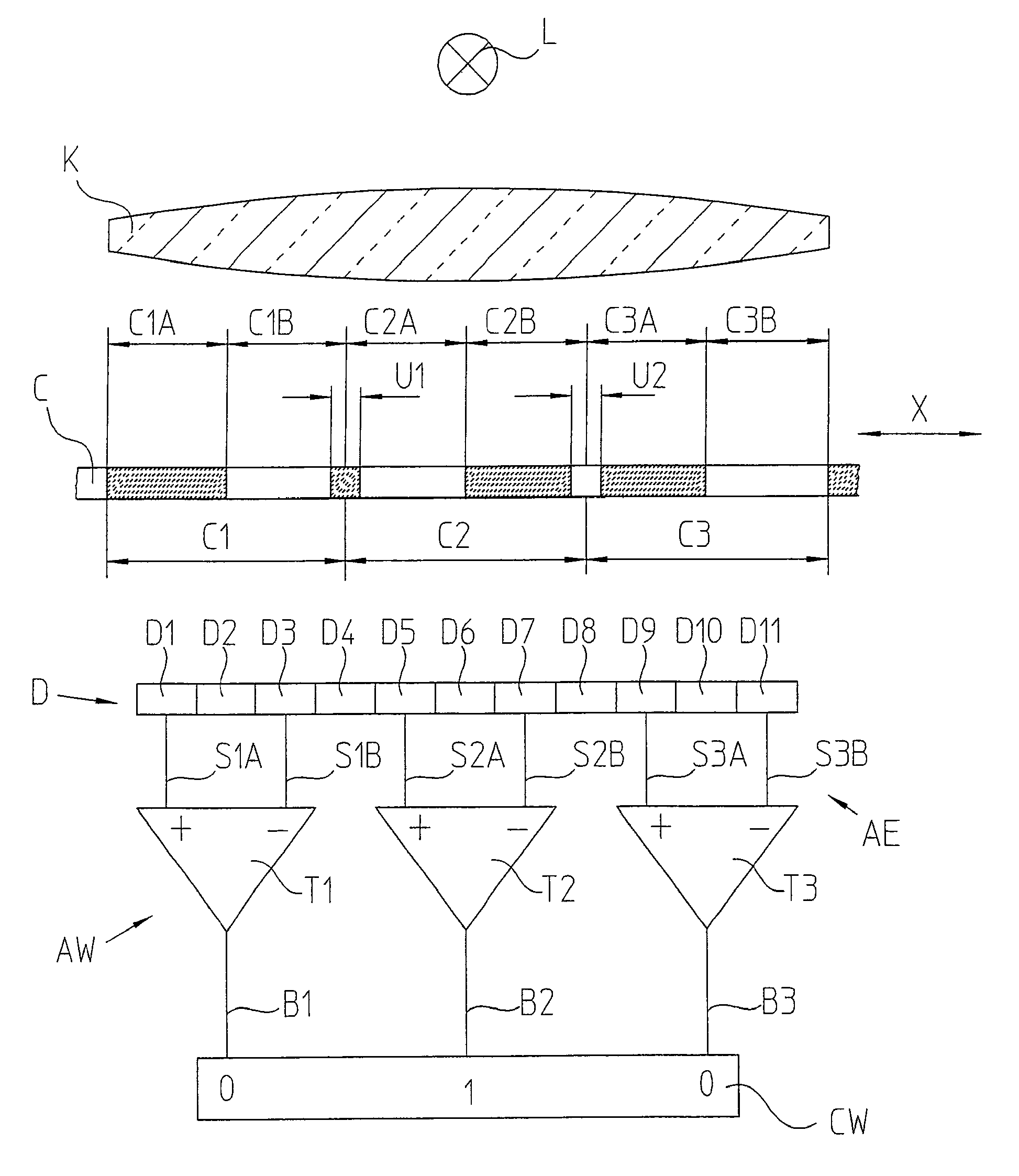
[0037]FIG. 1 schematically illustrates a position-measuring device arranged according to an example embodiment of the present invention, this position-measuring device corresponding largely to a position-measuring device described in German Published Patent Application No. 102 44 235, which is expressly incorporated herein in its entirety by reference thereto. This position-measuring device operates in accordance with the optical scanning principle in which a code C is scanned using the transmitted-light method. A scanning device AE, which is arranged in a movable manner relative to code C in measuring direction X, is used for scanning code C.

[0038]Code C includes a series of code elements C1, C2, C3 of equal length arranged one behind the other in measuring direction X. Each code element C1, C2, C3 includes two partial regions A and B of equal length, arranged adjacent to each other in direct succession in measuring direction X, which partial regions are configured to be complement...


PUM


Abstract

A position-measuring device includes a code, including a series of code elements arranged one behind the other in a measuring direction, in which at least two consecutive code elements respectively form a code word containing a position information item, and a scanning device having detector elements for reading the at least two code elements of the code that form a code word, and an evaluation device in which the code word having the current position information may be ascertained from the scanning signals of the detector elements. The scanning device and the code are arranged in a moveable manner relative to each other in the measuring direction. Between adjacent code elements, which have identical properties in the transition region, separating elements having complementary properties are inserted.

Description

CROSS-REFERENCE TO RELATED APPLICATIONS[0001]The present application claims priority to Application No. 10 2007 018 748.5, filed in the Federal Republic of Germany on Apr. 20, 2007, which is expressly incorporated herein in its entirety by reference thereto.FIELD OF THE INVENTION[0002]The present invention relates to a position-measuring device, e.g., for determining an absolute position.BACKGROUND INFORMATION[0003]In many areas, absolute position-measuring devices are increasingly used, in which the absolute position information is derived from a code track having code elements situated one behind the other in the measuring direction. For this purpose, the code elements are provided in a pseudo-random distribution such that a certain number of consecutive code elements respectively form one bit pattern. When shifting the scanning device with respect to the code track by a single code element, a new bit pattern is already formed and a sequence of varying bit patterns is available ov...

Claims


Application Information

Patent Timeline
Patent Type & Authority Patents(United States)
IPC IPC(8): G06F17/00
CPCG01D5/347G01D5/34792
Inventor MAYER, ELMAROBERHAUSER, JOHANNTOVAR, HEINZ
Owner DR JOHANNES HEIDENHAIN GMBH
Why Eureka
Try Eureka