Vascular closure device

a closure device and vascular technology, applied in wound clamps, medical science, surgery, etc., can solve the problems of requiring patients, affecting the healing effect of wounds, so as to reduce the spacing

Active Publication Date: 2014-09-02
COOK MEDICAL TECH LLC
View PDF19 Cites 18 Cited by
  • Summary
  • Abstract
  • Description
  • Claims
  • Application Information

AI Technical Summary

Benefits of technology

[0009]The anchor body of the closure device can be dimensioned such that the distal end is insertable through the opening to an interior space of the body vessel while the other end is external of the body vessel. The proximal end or the distal end of the anchor body can include at least one portion suitable for engagement with tissue at an exterior or interior of the body vessel to inhibit movement of the anchor body. The closure devices have hook-like extensions that grab tissue of the body vessel wall surrounding the opening. The hook-like extensions are designed to be flexible for manipulation in tissue and delivery, and yet rigid enough when extended to push the tissue engagement structures against the vessel wall. Once closure has been completed, the closure device may be removed or may be left in the body to be bioabsorbed. The closure device may also be coated with a suitable therapeutic agent to promote faster healing.
[0012]A method of closing an opening formed through a wall of a body vessel of a patient with one example of the first embodiment of the closure device is provided below. After inserting the first end of the anchor body through the opening, the anchor body can be moved into the extended configuration in the interior space of the body vessel. The retraction member can be withdrawn such that the hook members engage the body vessel wall. The tubular member can be advanced over a proximal portion of the anchor body to reduce spacing between the hook members and to capture the body vessel wall between the tubular member distal end and the hook members.

Problems solved by technology

The manual pressure method, however, can take half an hour or more and can require the patient to remain immobilized for at least that period of time and be kept in the hospital for observation.
Rate of post-puncture hemorrhage can be high leading to considerable complications.
There may also be a possibility for clots at puncture site to be dislodged.
Sutures may have procedure variability, but still require time to close the vessel.
It also may be difficult to perform the suturing in a key-hole procedure or in other types of surgery where there is limited access to the wound site.

Method used


Image

  • Vascular closure device
  • Vascular closure device
  • Vascular closure device

Examples


first embodiment

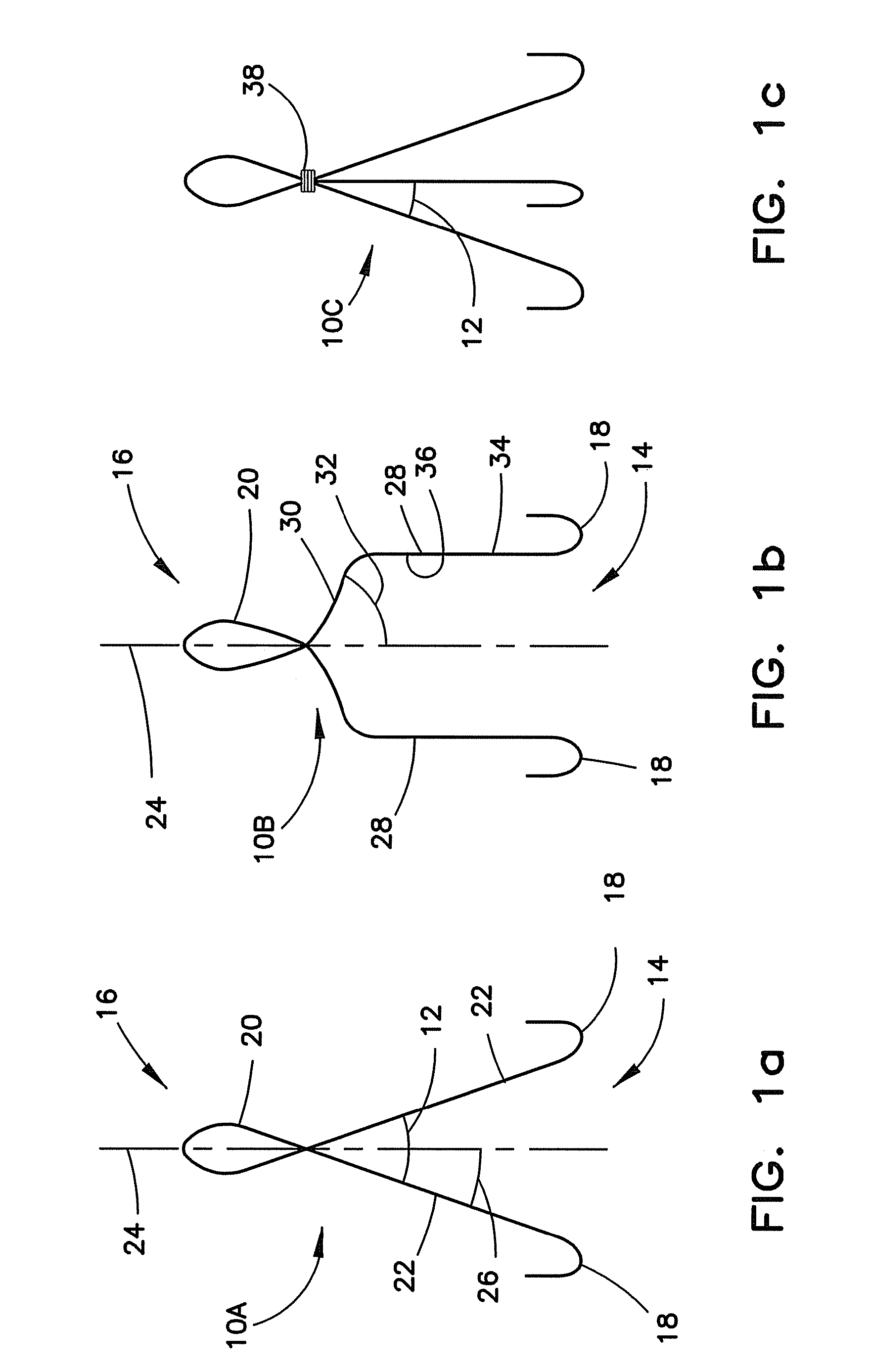
[0034]In each of the variations of the first embodiment, the closure device includes a plurality of hook members 12 having a first end 14 and a second end 16 to form the anchor body. The first end 14 is configured to engage the tissue surrounding the opening in the body vessel. The second end is configured to receive a retraction member as described below.

[0035]In FIG. 1a, the closure device 10A includes the hook members 12 that are shown as one continuous wire formed with hooks 18 at the first end 14, an eyelet 20 at the second end 16 and a substantially straight member 22 therebetween. The straight member 22 can be angled from a central axis 24 with an angle 26 suitable to permit movement away from the central axis 24 to position the hooks 18 to contact the surrounding area of the opening. In FIG. 1b, the closure device 10B includes the hook members 12 that are shown as one continuous wire formed with hooks 18 at the first end 14, an eyelet 20 at the second end 16 and a bent membe...

second embodiment

[0051]In FIG. 6a, the anchor body of the closure device 210A includes the hook members 212 that are shown as discrete wires formed with hooks 218 at the first end 214, a pointed end 220 at the second end 216 and a middle region 222 therebetween. The middle region 222 of the hook members 212 can each be attached at an attachment point 223 by wrapping the hook members 212 around each other, welding, soldering, or the like. The pointed end 222 can include additional material to form a tabbed end 225 for better engagement with a plug-like member. The portion of the middle region 222 that is near the first end can be angled from a central axis 224 with an angle 226 suitable to permit movement away from the central axis 224 to position the hooks 218 to contact the surrounding area of the opening. In FIG. 6b, the anchor body of the closure device 210B includes a similar structure as the closure device 210A except an eyelet 228 can be located between the hooks 218 and the attachment point 2...


PUM


Abstract

A device for closure of an opening formed through a wall of a body vessel of a patient is provided, as well as an introducer system for delivery of the closure device. Various embodiments include the closure device having hook members configured to engage the tissue interior of the body vessel wall, hook members configured to engage interstitial tissue adjacent to the body vessel, a plug member to contact sealably the opening from inside the body vessel, and combinations thereof. A retraction member is removably attached to the each of the embodiments to permit manipulation of the device. Remodelable material may be included with each of the embodiments to promote quicker healing. The introducer includes a sheath that is insertable through the opening and a pusher disposed within the lumen of the sheath and movable within the sheath lumen to deploy the device.

Description

BACKGROUND OF THE INVENTION[0001]1. Technical Field[0002]The present invention relates to a device for closing an opening formed in the wall of a body vessel while carrying out a medical procedure. More particularly, the invention relates to a vascular closure device for closing an opening during deployment of a medical interventional device into the vascular system.[0003]2. Background Information[0004]There are many medical procedures in which a tube, catheter, and / or wire is temporarily inserted into or out of a blood vessel. For example, the Seldinger technique is performed by inserting a hollow needle through a patient's skin and muscle tissue into the vascular system. It is preferable that the needle is passed through the entire vessel, and then pulled back at a steeper angle until blood from the blood vessel flashes in the needle but not all the way out. A guide wire is then passed through the lumen of the needle into the blood vessel. The needle is removed and an introducer s...

Claims


Application Information

Patent Timeline
Patent Type & Authority Patents(United States)
IPC IPC(8): A61B17/08A61D1/00A61B17/00
CPCA61B17/0057A61B2017/00592A61B2017/00668A61B2017/00601A61B2017/00623A61B2017/00004A61B2017/00778A61B2017/00615A61B2017/00579
Inventor SCHAEFFER, DARIN, G.
Owner COOK MEDICAL TECH LLC
Why Eureka
Try Eureka