
Laser-based flow modification to remotely control air vehicle flight path

a technology of remotely controlled air vehicles and flow modifications, applied in the direction of air-flow influencers, drag reduction, directed energy weapons, etc., can solve the problems of significant and lasting flow disruption on the targeted control surface, dramatic loss of lift, and strong reduction of li

Active Publication Date: 2014-09-09
KREMEYER KEVIN
View PDF26 Cites 12 Cited by
  • Summary
  • Abstract
  • Description
  • Claims
  • Application Information

AI Technical Summary

Benefits of technology

[0030]In some embodiments, the filamenting laser can deposit the energy along the leading edge by forming the laser filament parallel to the control surface leading edge.

Problems solved by technology

Seeding these frequencies, even very lightly, can lead to dramatic modification to the flow across the control surface, in particular, in loss of laminar flow, replaced by separated flow, leading to a strong reduction in lift, in fact leading to stall under the right conditions (or a dramatic loss in lift).
Performing this repeatedly / repetitively will ensure significant and lasting flow disruption on the targeted control surface.

Method used


Image

  • Laser-based flow modification to remotely control air vehicle flight path
  • Laser-based flow modification to remotely control air vehicle flight path
  • Laser-based flow modification to remotely control air vehicle flight path

Examples


examples

[0048]The following examples are given as particular embodiments of the invention and to demonstrate the advantages thereof. It is understood that the examples are given by way of illustration and are not intended to limit the specification or the claims that follow in any manner.

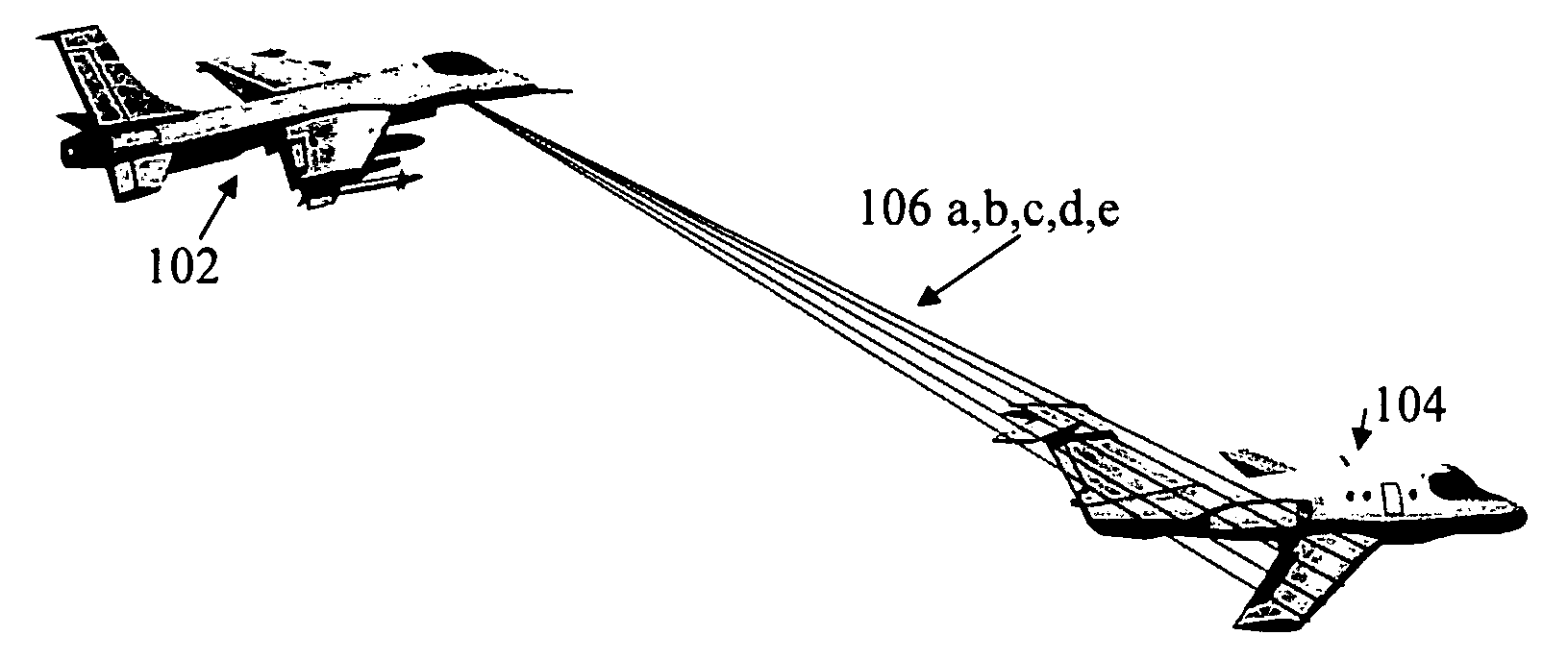
[0049]As is illustrated in FIG. 1, a chase plane (102) targets an air vehicle (104) with laser pulses (106a-e), rastered across the leading edge of a control surface.

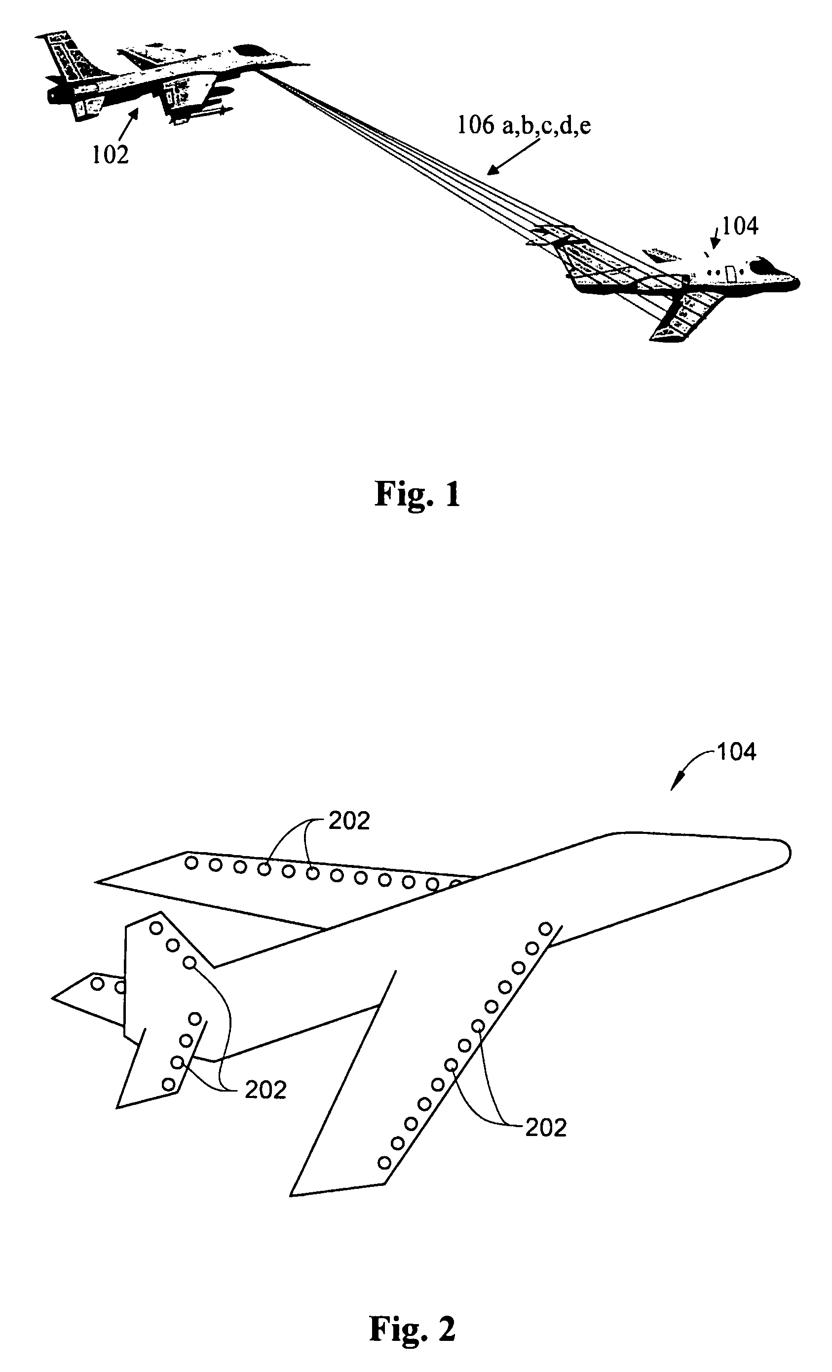
[0050]As is illustrated in FIG. 2, the leading edge of any control surfaces (202), including lifting and stabilizing surfaces can be targeted with rastered laser ablation spots.

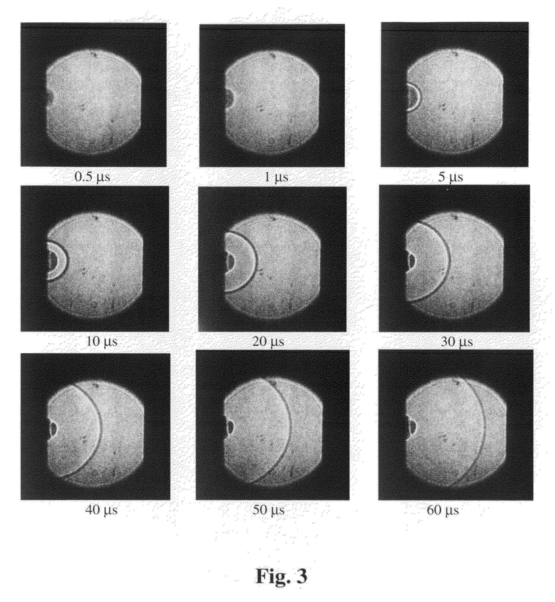
[0051]As is illustrated in FIG. 3, the laser ablation spots form when a surface (on left edge of each sub-figure shown at different times in the ablation evolution.). In this case, the energy deposition is on the order of hundreds of milliJoules, and the field of view is ˜1.5″, demonstrating a shockwave that expands over inches in tens of microseconds. As the shockwave p...


PUM


Abstract

Systems, equipment, and methods to deposit energy to modify and control air flow, lift, and drag, in relation to air vehicles, and methods for seeding flow instabilities at the leading edges of control surfaces, primarily through shockwave generation through deposition of laser energy at a distance.

Description

CROSS REFERENCE TO RELATED APPLICATION[0001]This application claims the benefit of priority from U.S. Provisional Patent Application No. 60 / 960,976, filed Oct. 23, 2007. The U.S. provisional application, in its entirety, is incorporated herein by reference.[0002]The following patents and patent applications are each incorporated herein by reference in their entirety:[0003]1) U.S. Pat. No. 6,527,221, which granted on Mar. 4, 2003, entitled “Shockwave Modification, Method and Apparatus and System;”[0004]2) U.S. Pat. No. 7,063,288, which granted on Jun. 20, 2006, entitled “Shockwave Modification, Method and System;”[0005]3) U.S. Pat. No. 7,121,511, which granted on Oct. 17, 2006, entitled “Shockwave Modification, Method and System;”[0006]4) U.S. patent application Ser. No. 11 / 288,425 filed on Nov. 29, 2005 and entitled “Shockwave Modification, Method and System;”[0007]5) U.S. patent application Ser. No. 11 / 540,964 filed on Oct. 2, 2006 and entitled “Shockwave Modification, Method and S...

Claims


Application Information

Patent Timeline
Patent Type & Authority Patents(United States)
IPC IPC(8): B64C23/00B64C19/00
CPCB64C2230/12Y02T50/166B64C19/00B64C23/005Y02T50/10F41H13/005
Inventor KREMEYER, KEVIN
Owner KREMEYER KEVIN
Learn More