
Golf club head or other ball striking device having custom machinable portions

a golf club and head technology, applied in the field of ball striking devices, can solve the problems of robbing the shot of distance, sending the ball in the wrong direction, and/or imparting undesired hook or slice spin, etc., and achieve the effect of lowering the total weight of the head

Active Publication Date: 2014-09-09
KARSTEN MFG CORP
View PDF24 Cites 52 Cited by
  • Summary
  • Abstract
  • Description
  • Claims
  • Application Information

AI Technical Summary

Benefits of technology

The invention relates to golf club heads, particularly ball striking devices, such as golf clubs. The heads have a unique design that includes a weight element that is connected to the body of the head. The weight element can be a single leg or a combination of legs that form a U-shaped or a four-legged structure. The weight element can be integrally formed with the body or located on the inner or outer surface of the body. The heads can be made with a target weight in mind, and the weight element can be removed or partially removed to achieve the target weight. The heads can be made of a metallic material or formed of a composite of metallic and non-metallic materials. The technical effects of the invention include improved weight distribution, reduced weight of the head, improved performance, and better aesthetics.

Problems solved by technology

Despite the various technological improvements, golf remains a difficult game to play at a high level.
Off-center hits may tend to “twist” the club face when it contacts the ball, thereby sending the ball in the wrong direction, imparting undesired hook or slice spin, and / or robbing the shot of distance.
Club face / ball contact that deviates from squared contact and / or is located away from the club's desired ball contact location, even by a relatively minor amount, also can launch the golf ball in the wrong direction, often with undesired hook or slice spin, and / or can rob the shot of distance.
Other golfers may tend to miss in other areas of the club face.

Method used


Image

  • Golf club head or other ball striking device having custom machinable portions
  • Golf club head or other ball striking device having custom machinable portions
  • Golf club head or other ball striking device having custom machinable portions

Examples


Embodiment Construction

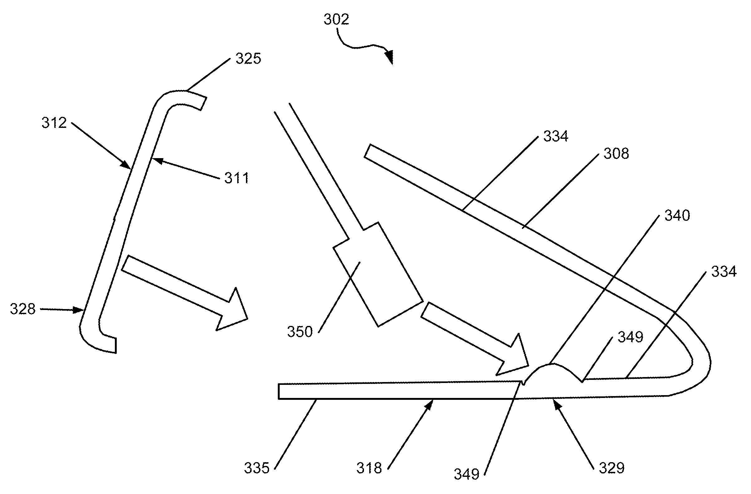
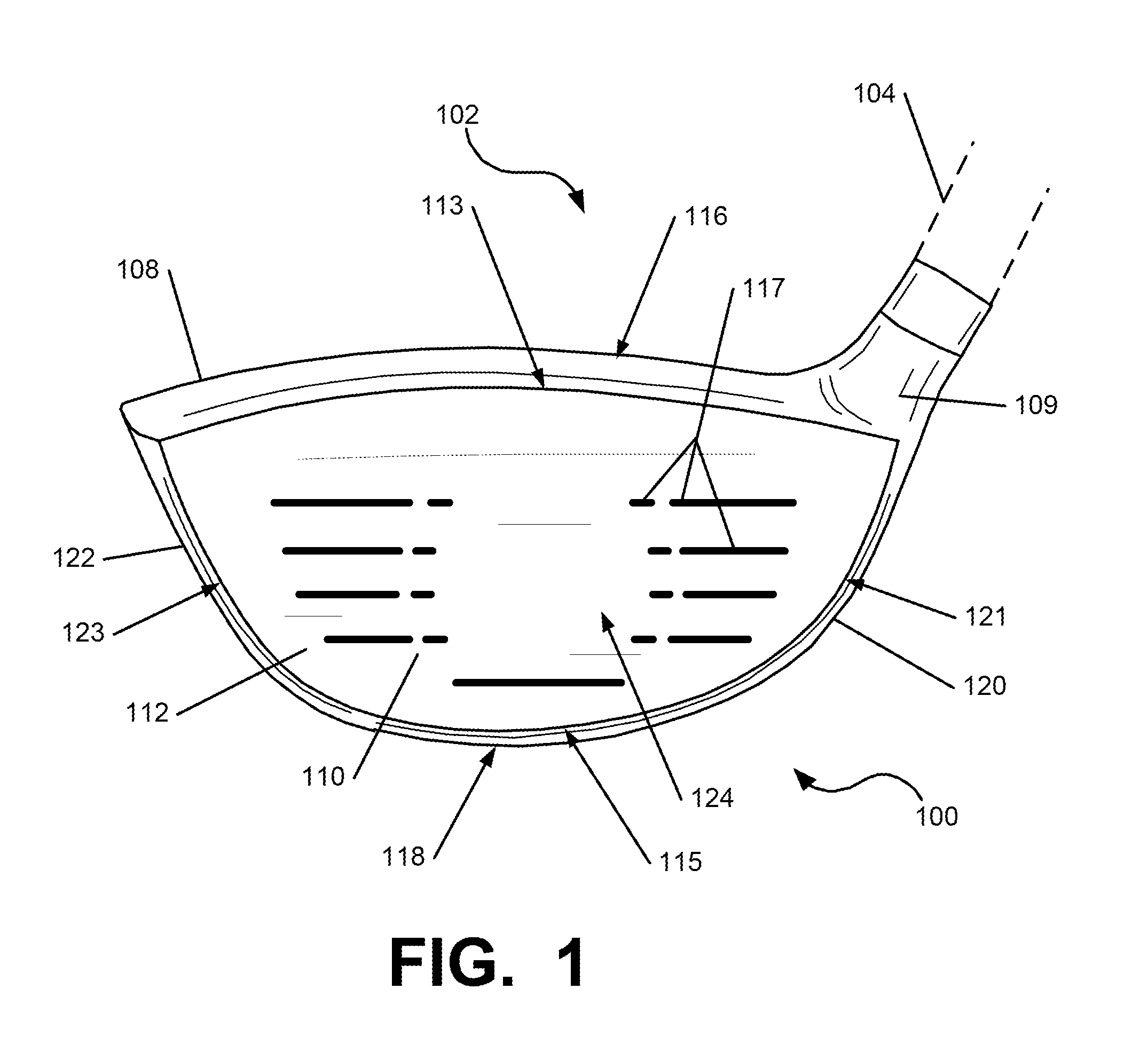
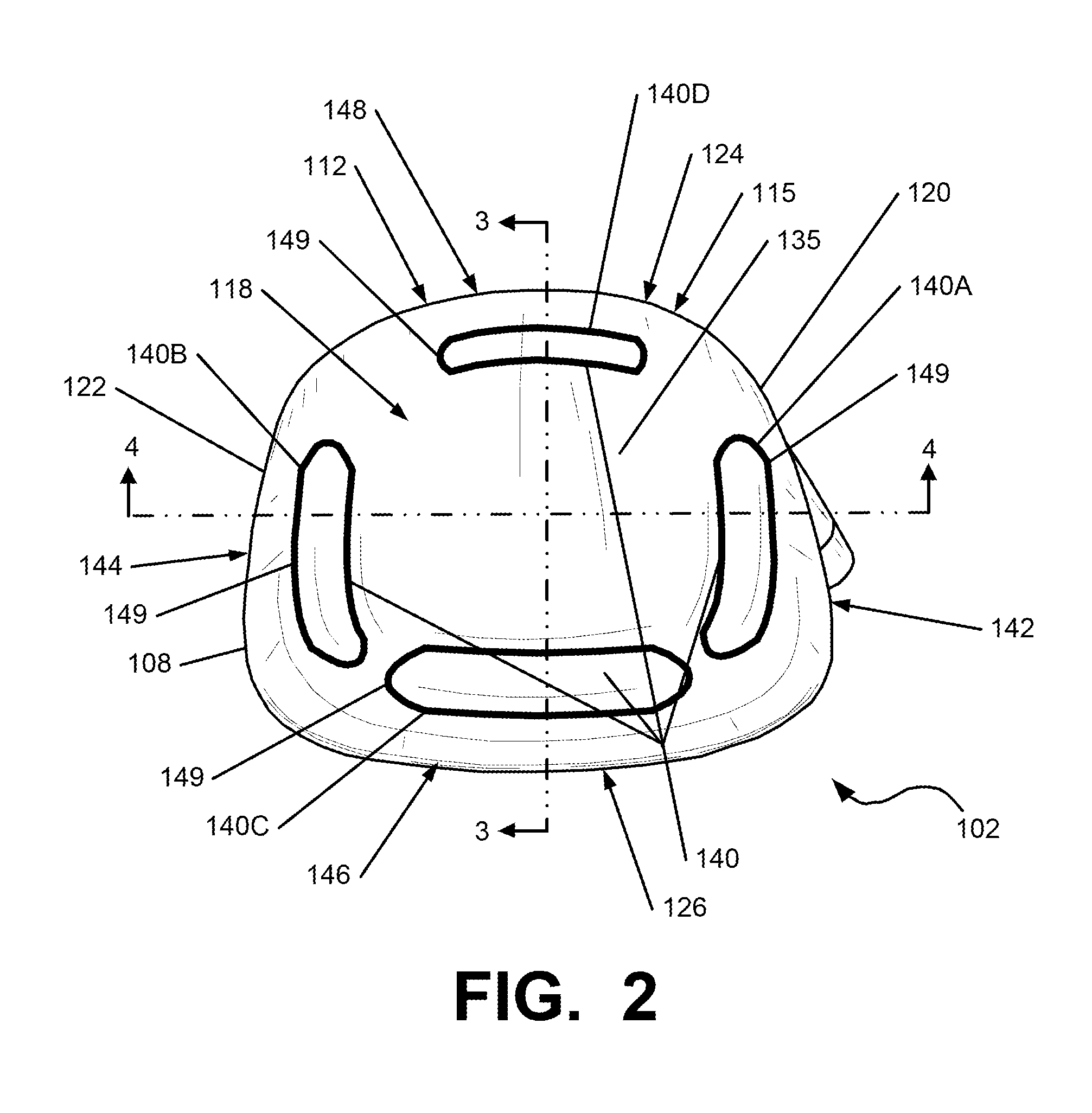
[0069]In the following description of various example structures according to the invention, reference is made to the accompanying drawings, which form a part hereof, and in which are shown by way of illustration various example devices, systems, and environments in which aspects of the invention may be practiced. It is to be understood that other specific arrangements of parts, example devices, systems, and environments may be utilized and structural and functional modifications may be made without departing from the scope of the present invention. Also, while the terms “top,”“bottom,”“front,”“back,”“side,”“rear,” and the like may be used in this specification to describe various example features and elements of the invention, these terms are used herein as a matter of convenience, e.g., based on the example orientations shown in the figures or the orientation during typical use. Additionally, the term “plurality,” as used herein, indicates any number greater than one, either disju...


PUM


Abstract

A ball striking device, such as a golf club, includes a head with a face having a ball-striking surface configured for striking a ball, a body connected to the face, and at least one weight element connected to the body. The head has a total weight that is higher than a target weight of the head, and the at least one weight element is configured to be at least partially removed by a material removal technique to lower the total weight of the head to approximately equal the target weight. The at least one weight element may be integrally connected to the body, such as being integrally formed with at least a portion of the body. The material removal technique may constitute milling, machining, or other material removal techniques or combination of such techniques.

Description

TECHNICAL FIELD[0001]The invention relates generally to ball striking devices, such as golf club heads, having one or more machinable weight elements connected to the head. Certain aspects of this invention relate to golf club heads having one or more weight elements configured to be at least partially removed by machining or another material removal technique to lower the total weight of the head to approximately equal a target weight.BACKGROUND[0002]Golf is enjoyed by a wide variety of players—players of different genders, and players of dramatically different ages and skill levels. Golf is somewhat unique in the sporting world in that such diverse collections of players can play together in golf outings or events, even in direct competition with one another (e.g., using handicapped scoring, different tee boxes, etc.), and still enjoy the golf outing or competition. These factors, together with increased golf programming on television (e.g., golf tournaments, golf news, golf histo...

Claims


Application Information

Patent Timeline
Patent Type & Authority Patents(United States)
IPC IPC(8): A63B53/04A63B53/06
CPCA63B53/04A63B53/0475A63B53/047A63B53/0466A63B2053/0433A63B2053/0491Y10T29/49995A63B2053/0412A63B2225/01Y10T409/303752B23C3/28A63B49/06A63B60/52A63B53/0412A63B53/0433A63B60/00
Inventor THOMAS, JAMES, S.
Owner KARSTEN MFG CORP
Learn More