Gear unit

a technology of gear unit and gear shaft, applied in the direction of gearing element, gearing detail, belt/chain/gearing, etc., can solve the problem of extremely low friction power loss, and achieve the effect of little expenditur

Active Publication Date: 2014-09-16
SEW-EURODRIVE GMBH & CO KG
View PDF81 Cites 8 Cited by
  • Summary
  • Abstract
  • Description
  • Claims
  • Application Information

AI Technical Summary

Benefits of technology

[0005]It is advantageous in this regard that oil adhering to the front is able to be scraped off and that the kinetic energy of the oil is utilizable. For scraping off the oil may be implemented passively, that is, without an additional source of energy. The power loss arising in the form of friction power is extremely low when the gear wheel is disposed in an industrially utilizable gear unit having a nominal power of more than 10 watts. The kinetic energy may be rendered utilizable in various manners. On the one hand, oil may thus be transported for cooling purposes, while on the other hand the oil may also be transported upwards, that is, the oil may be supplied with potential energy, for storing the oil temporarily in a temporary storage unit for lowering the oil level in operation.
[0057]In example embodiments, an input shaft is provided to be sealed against the housing part, in particular against the pot-shaped housing part, by a shaft sealing ring. It is advantageous in this regard that oil may be prevented from escaping.

Problems solved by technology

The power loss arising in the form of friction power is extremely low when the gear wheel is disposed in an industrially utilizable gear unit having a nominal power of more than 10 watts.

Method used


Image

  • Gear unit
  • Gear unit
  • Gear unit

Examples


Embodiment Construction

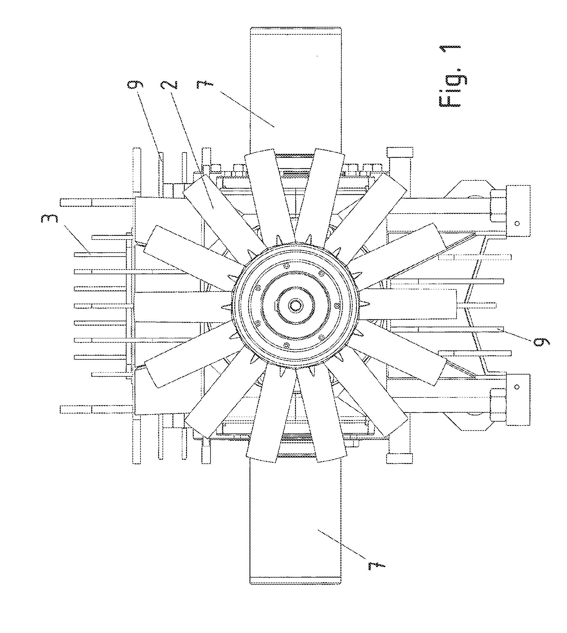
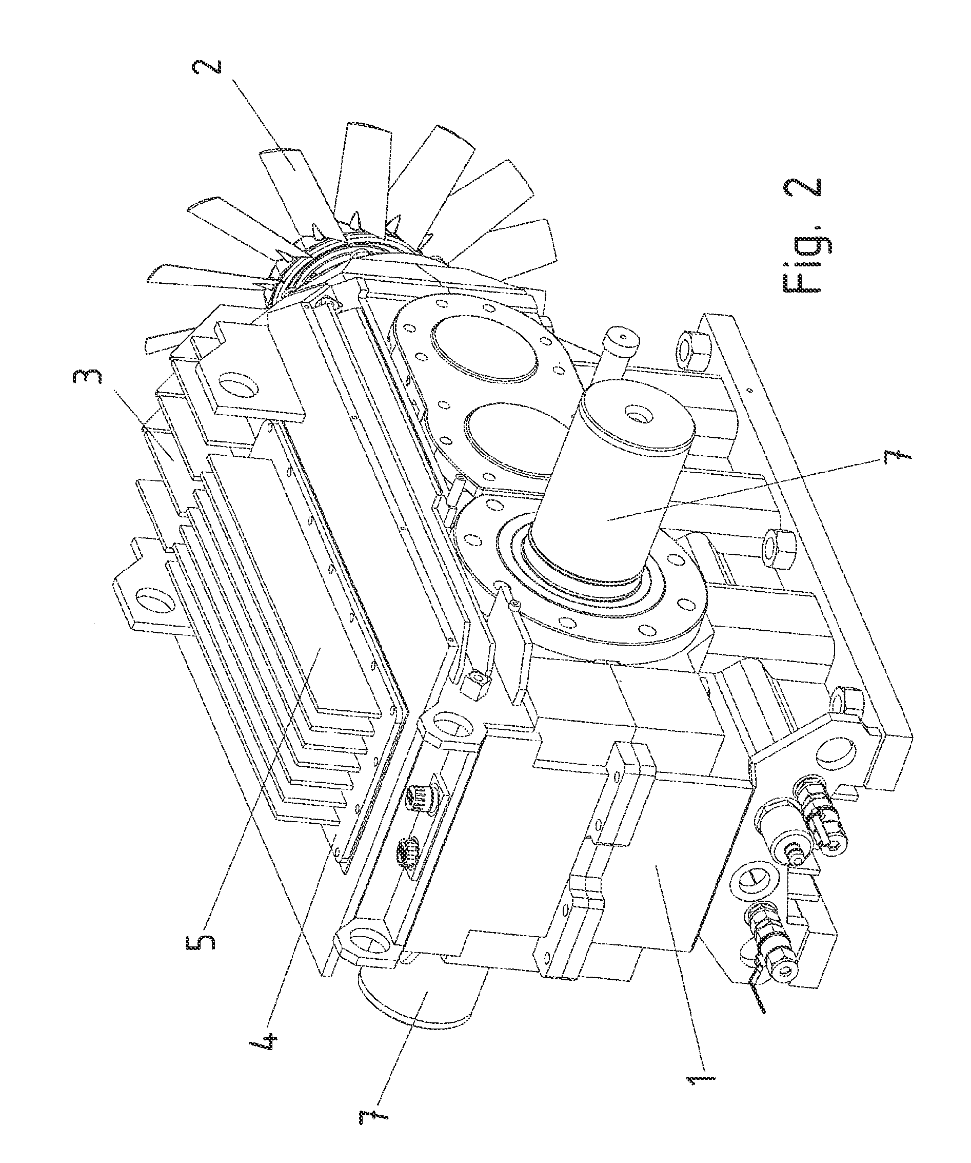
[0126]In the exemplary embodiment shown in FIGS. 1 through 3, a fan impeller 2 is connected on the input shaft in a rotationally fixed manner. The fan impeller is thus operated at a suitably high rotational speed and produces a powerful air flow using its fan impeller vanes when the gear unit is operated at the nominal rotational speed. The higher the rotational speed and the torque, the higher is also the power loss, that is, the thermal power to be dissipated to the surroundings.

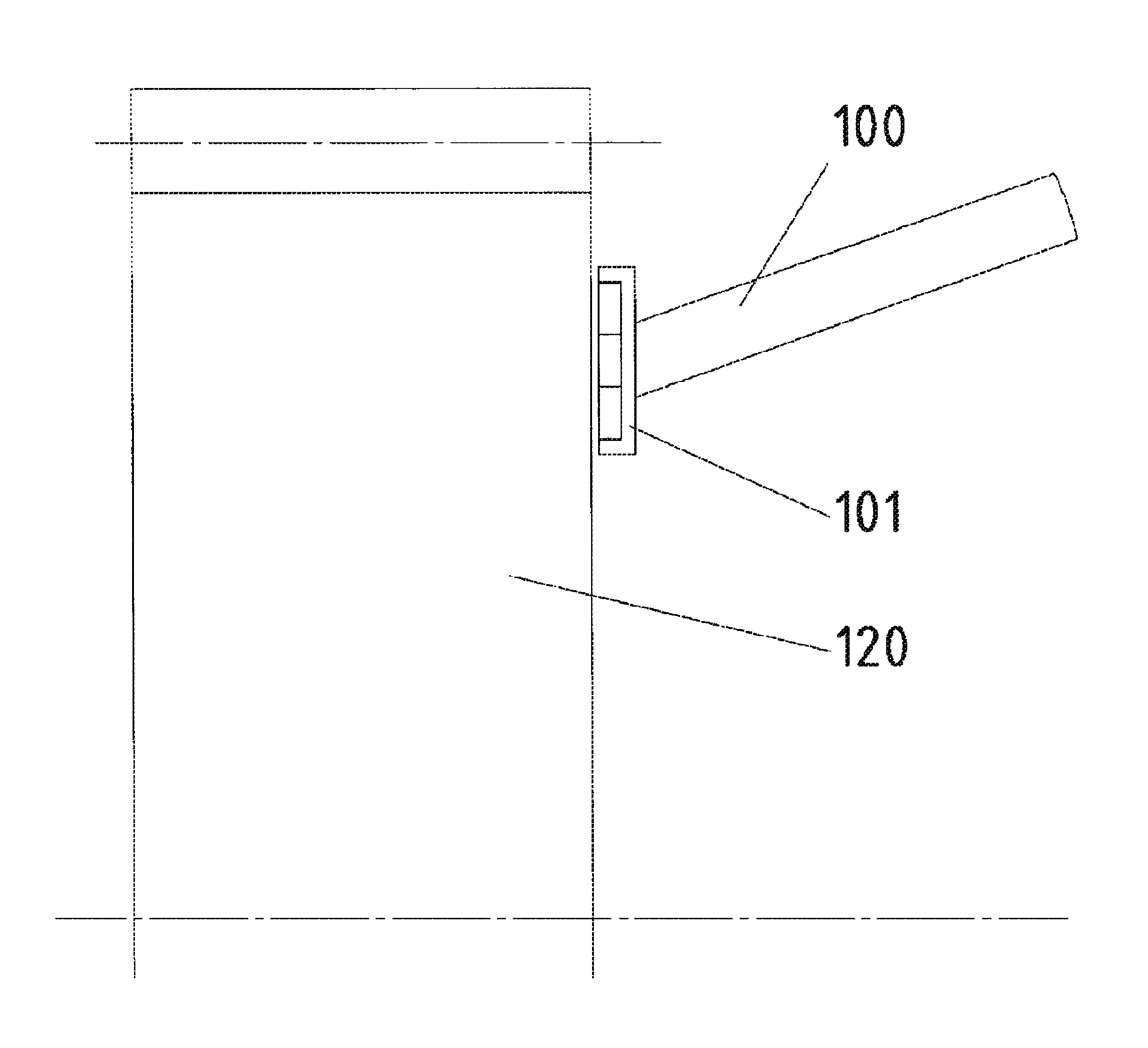
[0127]The cooling air flow produced by fan impeller 2 is conducted along a slanted housing area 8. This is either produced by mounting suitably formed pieces of sheet metal and connecting them to housing part 1 or alternatively by forming housing part 1 suitably, which may be accomplished without special additional effort particularly in the case of an input right-angle gear stage.

[0128]Furthermore, cooling fins 6 are provided on slanted housing area 8 and cooling fins 3 and 9 on housing part 1.

[0129]A hou...


PUM


Abstract

A gear unit, an oil scraping device being provided on the front of a rotatably supported gear wheel, in particular on a plane area of the front of a gear wheel.

Description

FIELD OF THE INVENTION[0001]The present invention relates to a gear unit.BACKGROUND INFORMATION[0002]It is known that gear units having oil lubrication are practicable, the oil, that is, fluid, collecting in the lower part of the interior of the gear unit when the gear unit is not in operation, that is, when the gears are at rest, where it forms the oil sump that has an oil level corresponding to the filling level when filling in the oil. When operating the gear unit, in particular at the nominal speed of the input shaft and / or output shaft, the toothed parts of the gear unit spray and centrifuge the oil around. In particular, the mutually engaged toothings also spray out oil.SUMMARY[0003]Example embodiments of the present invention provide a gear unit such that as much power as possible is transmittable per unit volume.[0004]Among features of example embodiments of the present invention in the gear unit are that an oil scraping device is situated on the front of a rotatably support...

Claims


Application Information

Patent Timeline
Patent Type & Authority Patents(United States)
IPC IPC(8): F16H57/02F16H57/04F16H61/00
CPCF16H57/0447F16H57/045F16H57/0471F16H57/0495F16H57/0423F16H57/0493F16H57/0416Y10T74/2186Y10T74/19991Y10T74/2189F16H57/0413F16H57/0434F16H57/0452
Inventor STRAU.BETA., DIETMARSCHUTTERLE, INGO
Owner SEW-EURODRIVE GMBH & CO KG
Why Eureka
Try Eureka