Hybrid energy plant

a hybrid energy and energy plant technology, applied in water-power plants, machines/engines, electric generator control, etc., can solve the problems of increasing the unit cost of produced energy, the energy of both types is not captured in an efficient manner, and the prior art technology is not optimized for capturing energy of both types simultaneously. , to achieve the effect of preventing overload, limiting buoyancy, and preventing overload

Inactive Publication Date: 2018-11-20
SUS ENERGY
View PDF22 Cites 0 Cited by
  • Summary
  • Abstract
  • Description
  • Claims
  • Application Information

AI Technical Summary

Benefits of technology

[0011]The object of the invention is to provide new solutions for providing an energy plant, with which the problems of the prior art energy plants can be avoided or reduced.
[0012]The object of the invention is specifically to provide a plant with better than prior art efficiency by capturing simultaneously energy from both potential and kinetic sources of the waves and possible currents in a more effective manner. Kinetic energy capture is optimized by moving surfaces having velocity profiles matching to the flow speed of water particles in different distances from water surface. The plant may also provide means to follow tidal surface level changes thus keeping the flow capturing devices in the highest flow speed zone having highest energy density. Further the plant can be self orienting against incoming waves' direction. The plant may have a capability to limit excessive waves' loads in survival condition.

Problems solved by technology

Prior art technology does not capture both energy types simultaneously in an efficient manner.
Most energy plants are not optimized for capturing energy of both types simultaneously.
This makes them inefficient and increases unit cost of produced energy.
Also movements opposite to water flow in some areas of the moving objects cause very high internal loads to the structures and unnecessary reaction forces to the supporting structures, requiring uneconomical over-sizing of the structures.
However, certain problems are related to this prior art structure.
Not following the velocity profile of water in different depths causes excessive forces to the structures when flap motion reaches either end position and stops.
Another problem relates to a rigid float of the structure.
Wave crests have arbitrary lengths, and a rigid float causes extreme loads to the proposed support tower when one end is on the wave crest and the other on through.
This orientation is known to produce extreme high loads to a floating object, known in shipbuilding as sagging and hogging, depending on the wave crest and through positions along the floating object, and also pitching movement which causes extreme loads to supports limiting the movement.
Incorrectly dimensioned ships without any penetrations break in these circumstances and a ship size object forced to follow a stationary column penetrating through it has severe structural problems on the penetration area and in the column.
There is a further problem which relates to prior art energy plants which are anchored permanently to the sea bed.
Permanent bottom anchoring of a solid flap or wing does not allow the plant to reach the best surface energy flux in high tide.
Current technology level of wave power plants is still in the testing phase of innovations, and therefore routine maintenance and plant life time economics has not been an important driver.
Underwater maintenance is impossible in harsh weather due to rapid flows and violent plant movements.
The productivity of an energy plant is thus reduced further even due to minor technical problems.
A further problem with prior art wave energy plants relates to currently used gas-pressurized accumulators.
The storage capacity available for filtering power ripple is inadequate, causing the output power to alter according to the waves.
This makes the wave power difficult to utilize in common grid without additional arrangements.
As a consequence, the prior art wave energy plants do not have optimal efficiency, they are easily damaged in the harsh weather, and they are difficult to maintain.

Method used


Image

  • Hybrid energy plant
  • Hybrid energy plant
  • Hybrid energy plant

Examples


Embodiment Construction

[0056]The presented figures are not to scale, and component dimensions naturally vary according to requirements in different applications.

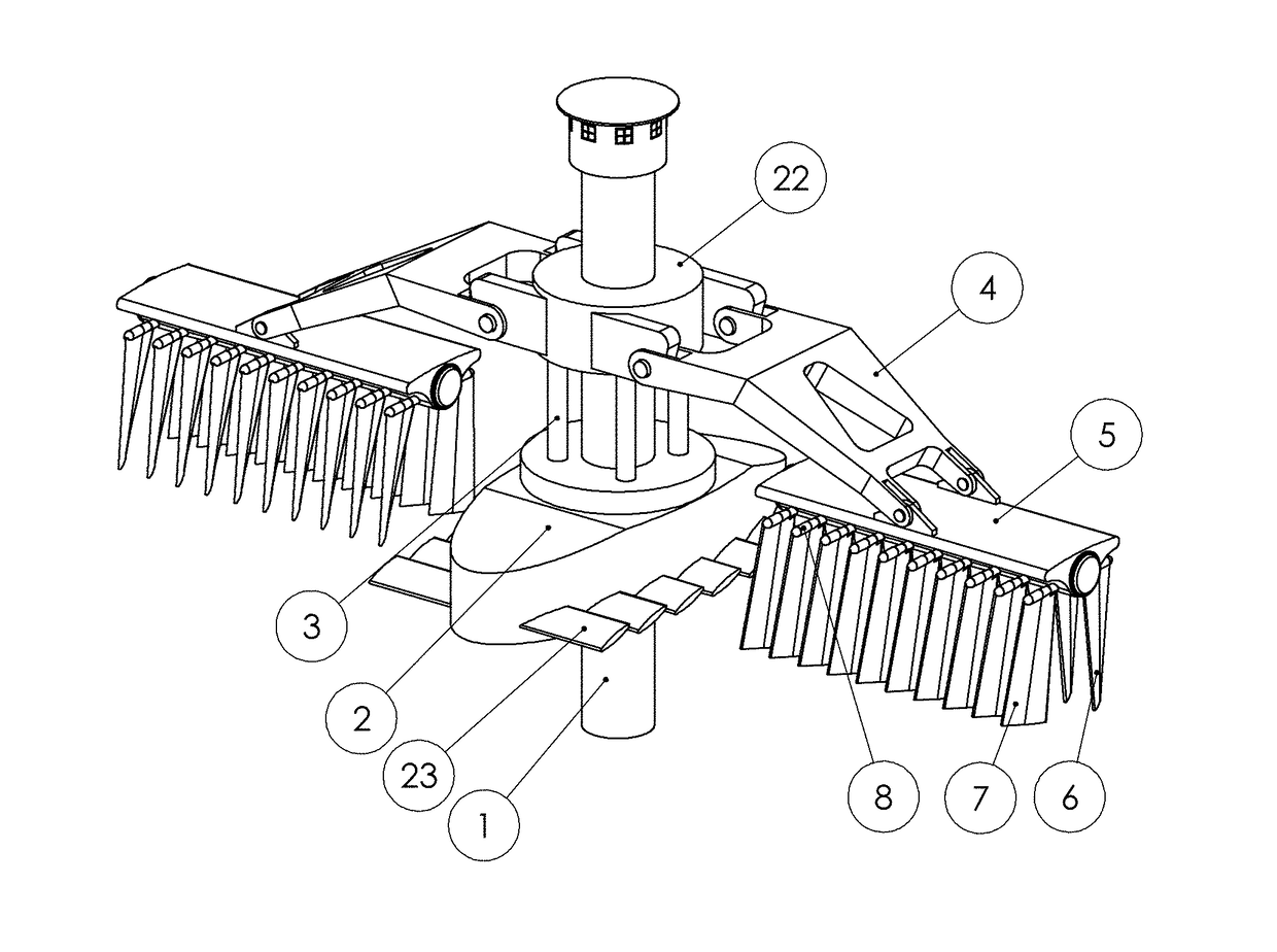
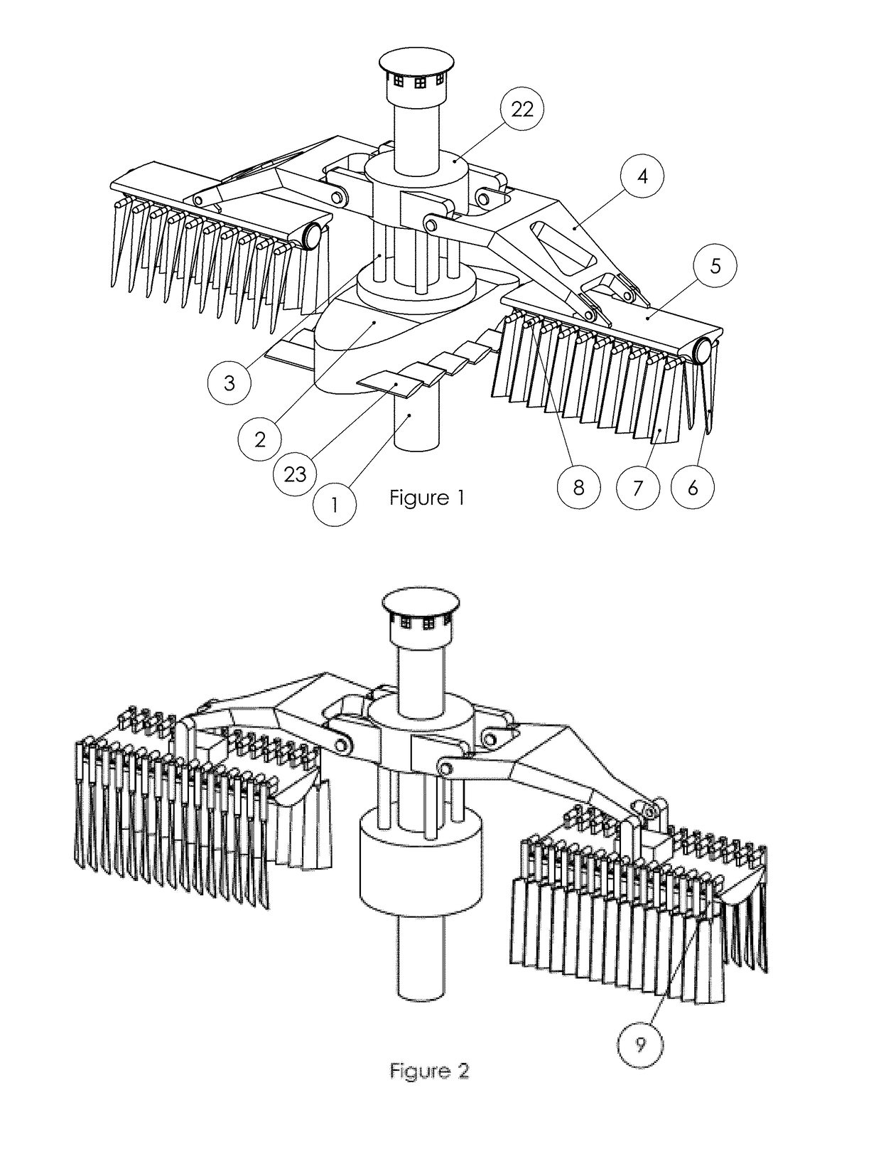
[0057]FIG. 1 illustrates an exemplary embodiment of a energy plant according to the invention. The plant captures potential energy from waves with wave floats 5, which follow the water surface height changes caused by waves. Connected to the floats, the plant has wing arrays 6 and 7 for capturing kinetic energy from waves, tidal or other streams or from combination of them.

[0058]The plant has a supporting column 1 around which the tidal compensation float slides and rotates. The tidal compensation float consists of partly or totally submerged part 2, connecting part 3, and upper part 22. The connecting part3 has small waterline area to minimize buoyancy changes due to waves thus keeping the compensation float on steady height. Arms 4 hold the floats 5 and wing arrays 6 and 7. Wings are connected to the floats with wing hubs 8. The supporting colum...


PUM


Abstract

The invention pertains to energy production by capturing simultaneously water potential (surface height differences due to waves) and kinetic (flow of water due to e.g. waves, tide or streams) energy. The plant can have tidal compensation (2, 3, 22, 23) to avoid energy flux streaming over the plant in high tide, and directional stabilizing arrangement to turn it automatically parallel to wave crests. Surfaces capturing energy from flow have optimized movements to follow speed of water in different depths. Also energy conservation to filter output ripple can be arranged with twin-phase fluid accumulators (51, 55).

Description

FIELD OF INVENTION[0001]This invention pertains to energy production by capturing simultaneously water potential energy and water kinetic energy. The potential energy relates to surface height differences due to waves, and kinetic energy relates to flow of water due to e.g. waves, tide or streams.BACKGROUND TECHNOLOGY[0002]Energy in ocean waves exists in two forms: potential energy generating water surface height differences which we see as waves and kinetic energy which moves the water particles back and forth. The energy is split equally between these two forms. More detailed description can be found from Dominic Reeve, Andrew Chadwick and Chris Fleming's book “Coastal Engineering, Processes, Theory and Design Practice”, second edition, 2012, Spoon Press, London and New York, ISBN 978-0-415-58352-7.[0003]Prior art technology includes capturing energy from wave potential energy with different floating objects like buoys. Prior art technology also includes capturing energy from wate...

Claims


Application Information

Patent Timeline
Patent Type & Authority Patents(United States)
IPC IPC(8): F03B17/02E02B9/08F03B13/16H02P9/04F03B13/12F03B13/10F03B13/18F03B13/20
CPCE02B9/08F03B13/16F03B13/1815Y02E10/38F05B2240/95F05B2260/406Y02E10/28F05B2240/912Y02E10/30F03B13/182Y02E10/20
Inventor SILTALA, TIMOKAUHANEN, AKI
Owner SUS ENERGY
Why Eureka
Try Eureka