Filtering device and a method of filtering a fluid

a filtering device and fluid technology, applied in gravity filters, centrifuges, loose filtering material filters, etc., can solve the problems of corrosion and wear, unreliability of high pressure feeding pumps, and conventional reverse osmosis, so as to improve the ability of regaining energy

Inactive Publication Date: 2014-07-15
AQUA MUNDUS
View PDF10 Cites 0 Cited by
  • Summary
  • Abstract
  • Description
  • Claims
  • Application Information

AI Technical Summary

Benefits of technology

[0010]Such a centrifugal filtering device recovers kinetic energy from the filtrate by means of the design of the outer wall of the rotating centrifuge body in an efficient manner. The centrifugal filtering device disclosed herein thus uses lower energy by recovering kinetic energy from the concentrate as well as from the filtrate.
[0014]According to an embodiment, the centrifugal filtering device further comprises walls attached to the outer casing and located in the outer space, the walls being configured to enhance the transfer of the kinetic energy from the filtrate to the outer casing. The walls assist in decelerating the rotating movement of the filtrate during the transport of the filtrate from the radially outer position to the radially inner position. The kinetic energy may thereby be transferred from the filtrate to the outer casing more efficiently.
[0020]According to an embodiment, the drive means is connected to the inner casing. The drive means is thereby able to rotate the inner casing about the central axis.
[0023]According to a further embodiment, the member comprises a transmission mechanism connected to the inner casing and the outer casing, thereby permitting the outer casing to rotate at a second rotational speed, the first rotational speed being greater than the second rotational speed. By rotating the outer casing at a lower rotational speed than the inner casing, energy losses due to friction against the air may be reduced. The transmission mechanism is configured to permit transfer of the regained mechanical energy from the outer casing to the inner casing. As described above, a significant part of the mechanical energy that is lost when rotating the inner casing may thereby be regained.
[0031]Advantageously, other fluids in need of filtration may be filtrated by the centrifugal filtering device of the invention, the device having the advantage of an improved capability of regaining energy compared to other known centrifugal filtering devices.

Problems solved by technology

Conventional reverse osmosis of sea water has several disadvantages, one of these being the known unreliability of the high pressure feeding pumps as they are often subjected to corrosion and wear problems.
However, the principal disadvantage of the conventional reverse osmosis process is the energy being wasted due to the discharge of the high pressure concentrate.
Conventional reverse osmosis devices with the extra function of recovering some of this wasted energy are known, however not wide spread due to the additional cost and complexibility.

Method used


Image

  • Filtering device and a method of filtering a fluid
  • Filtering device and a method of filtering a fluid
  • Filtering device and a method of filtering a fluid

Examples


first embodiment

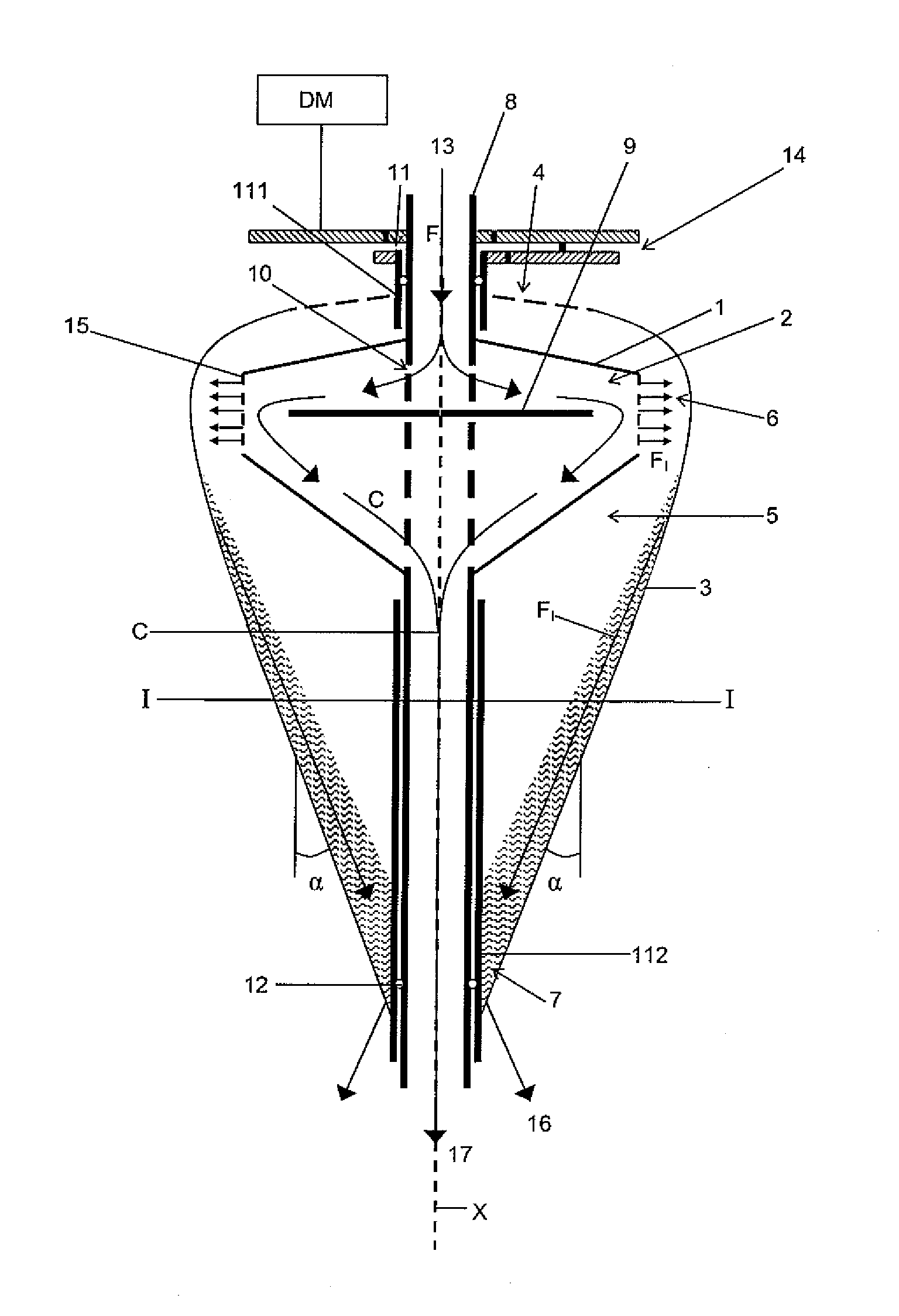
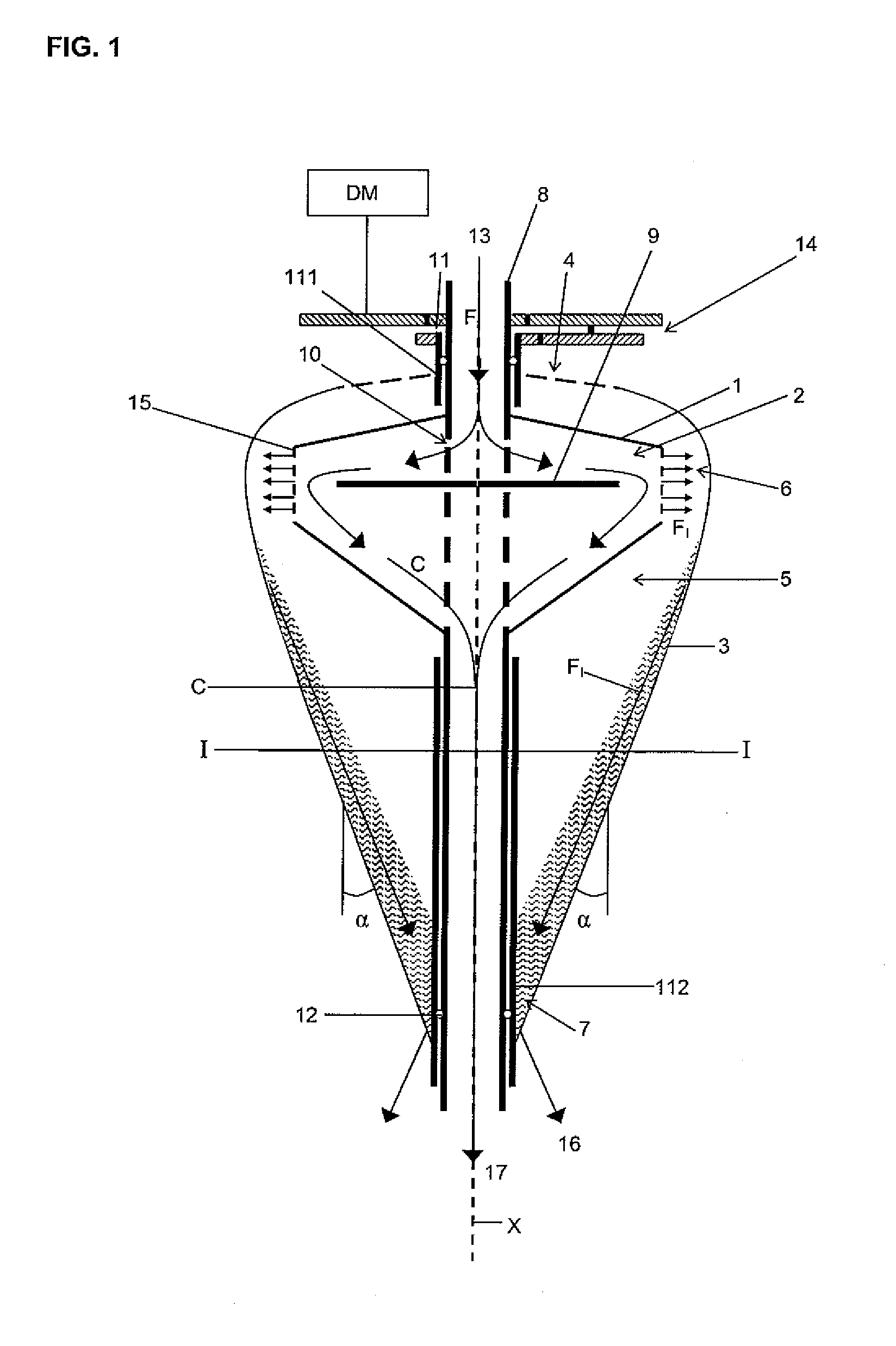
[0037]a centrifugal filtering device will now be described with reference to FIG. 1. The centrifugal filtering device comprises an inner casing 1. The inner casing 1 forms an inner space 2 with an inner pressure. Outside the inner casing 1 an outer casing 3 is located. The outer casing 3 comprises one or more openings 4, forming air vents to the surrounding air. The outer casing 3 forms an outer space 5 outside the inner casing 1. The outer space 5 comprises a radially outer position, or region, 6 and a radially inner position, or region, 7. Furthermore, the outer space 5 has an outer pressure. The inner casing 1 is connected to and provided around an inner axle 8. The inner axle 8 is hollow, permitting a fluid to flow through the inner axle 8. The inner axle 8 comprises a blocking wall 9. The blocking wall 9 extends through the inner axle 8 and preferably out into the inner space 2. Furthermore, the inner axle 8 has openings 10 to the inner space 2. The inner casing 1 is via the in...

fourth embodiment

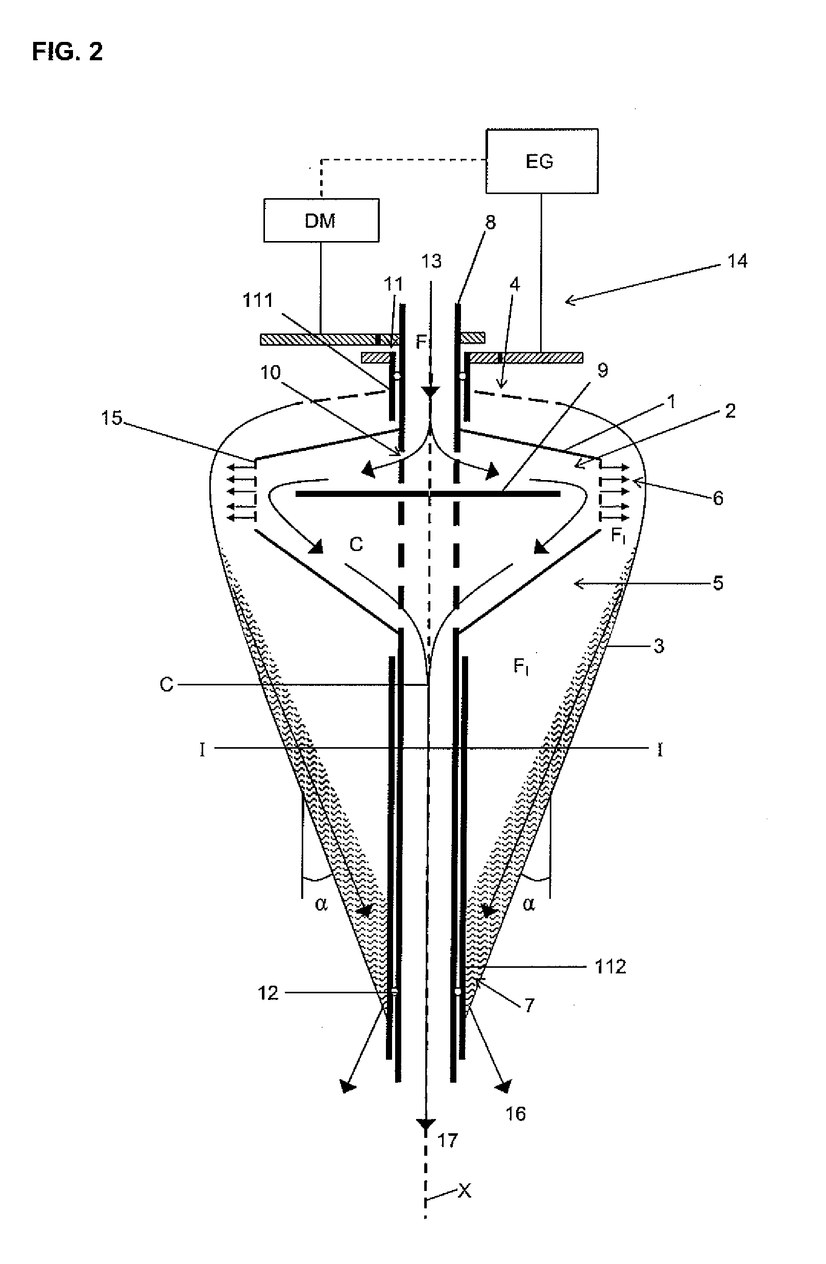
[0054]The decrease of the rotational speed is obtained in a manner wherein the kinetic energy of the filtrate FI is regained, the method thereby being energy efficient. The outer casing 3 is connected to a member 14 that is configured for regaining of mechanical energy from the outer casing 3. In this fourth embodiment, the member 14 comprises or consists of an arrangement comprising a weight or weights W. The decrease of the rotational speed can for example be obtained by moving the weight W attached to the inner axle 8 and the outer axle 11 from a first oscillating radius 19 to a second oscillating radius 20, the second oscillating radius 20 being larger than the first oscillating radius 19. The rotational speed will decrease whilst the moment of inertia is conserved and the filtrate FI can flow down the outer casing 3 and may be discharged through the filtrate outlet 16. Kinetic energy of the filtrate FI is thereby transferred to the weight W and regained as mechanical energy. Wh...


PUM

PropertyMeasurementUnit
pressureaaaaaaaaaa
mechanical energyaaaaaaaaaa
rotational speedaaaaaaaaaa

Abstract

The invention concerns a centrifugal filtering device for filtering a fluid. The device comprises a rotatable inner casing forming an inner space and a rotatable outer casing forming an outer space. The device further comprises a fluid inlet, at least one filter and drive means. The drive means is configured to rotate the inner casing to create a centrifugal pressure. The pressure forces a part of the fluid contained in the inner space through the filter and to a radially outer position of the outer space. The filtered fluid forms a filtrate, the filtrate having a kinetic energy. The outer casing is configured to transport the filtrate from the radially outer position to a radially inner position of the outer space, permitting transfer of the kinetic energy from the filtrate to the outer casing, thereby permitting regaining of mechanical energy.

Description

FIELD OF THE INVENTION[0001]The present invention concerns a centrifugal filtering device for filtering a fluid, wherein the centrifugal filtering device comprises an inner casing forming an inner space with an inner pressure and an outer casing forming an outer space with an outer pressure, wherein the inner casing and the outer casing are rotatable around a central axis extending through the inner casing and the outer casing, a fluid inlet configured to permit feeding of the fluid into the inner space, at least one filter being located between the inner space and the outer space, and drive means configured to rotate the inner casing at a first rotational speed in the inner space to create a centrifugal pressure forcing at least a part of the fluid from the inner space through the filter and to a radially outer position of the outer space, the filtered fluid forming a filtrate and the non-filtered fluid forming a concentrate, the filtrate having a rotating movement and a kinetic en...

Claims


Application Information

Patent Timeline
Patent Type & Authority Patents(United States)
IPC IPC(8): B04B7/16B01D61/06B01D61/08B01D63/16B04B7/14B04B9/04B04B9/06C02F1/38C02F1/44C02F9/08
CPCB01D61/025B01D61/06B01D63/16B01D2313/08B01D2313/12B01D2313/20B01D2313/24B01D2315/02C02F1/385C02F1/441C02F2103/08Y02A20/131
Inventor MARELIUS, FREDRICK
Owner AQUA MUNDUS
Why Eureka
Try Eureka