Electrical connector assembly with compact configuration

a technology of electrical connectors and assembly parts, applied in the direction of coupling device details, coupling device connections, coupling parts engagement/disengagement, etc., can solve the problems of inability to easily attach the metallic latch to the housing, the data transmitting rate might not meet the requirements of more and more higher data transmitting rate requirements of the server, and the internal room of the communication device will be smaller. , to achieve the effect of high data transmitting rate, simple latch mechanism and high density configuration

Active Publication Date: 2014-09-16
HON HAI PRECISION IND CO LTD
View PDF31 Cites 12 Cited by
  • Summary
  • Abstract
  • Description
  • Claims
  • Application Information

AI Technical Summary

Benefits of technology

[0005]Accordingly, an object of the present invention is to provide an electrical connector assembly having high-density configuration, high data transmitting rate, and a simple latch mechanism.

Problems solved by technology

Thus, the internal room of a communication device will be getting smaller.
However, such data transmitting rate might not meet more and more higher data transmitting rate requirements of the server.
Furthermore, the metallic latch has a complicated structure and cannot be easily assembled to the housing.

Method used


Image

  • Electrical connector assembly with compact configuration
  • Electrical connector assembly with compact configuration
  • Electrical connector assembly with compact configuration

Examples


Embodiment Construction

[0017]Reference will now be made to the drawing figures to describe the present invention in detail.

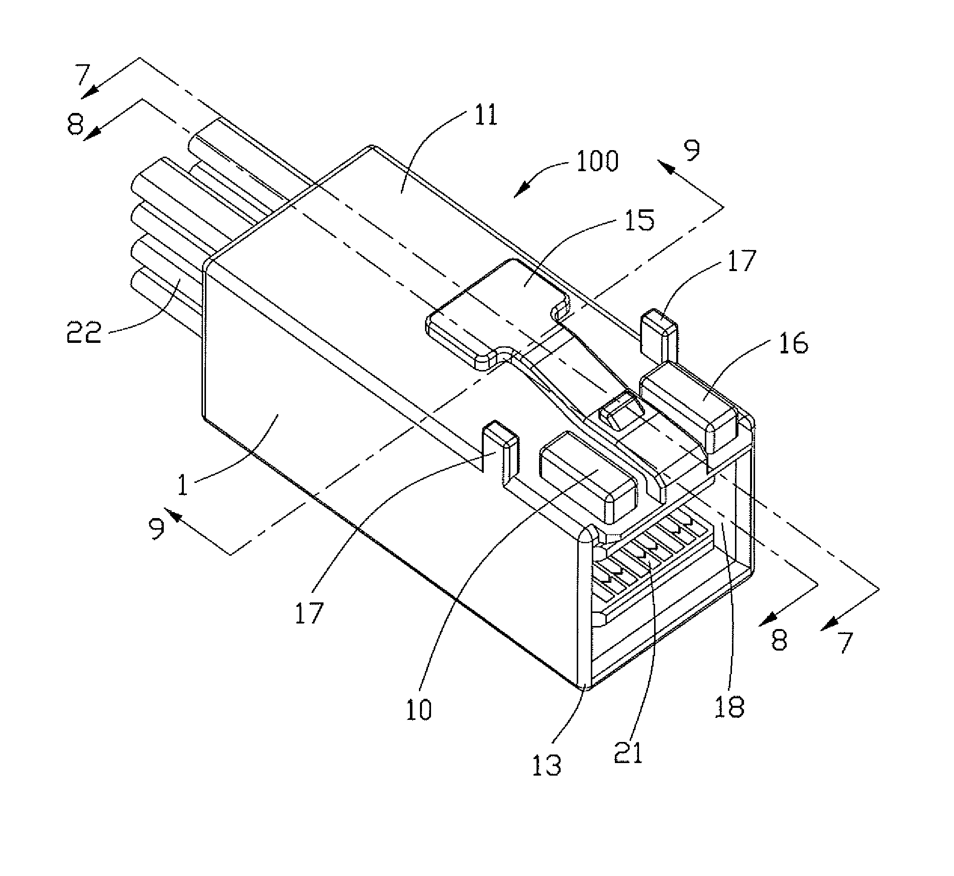
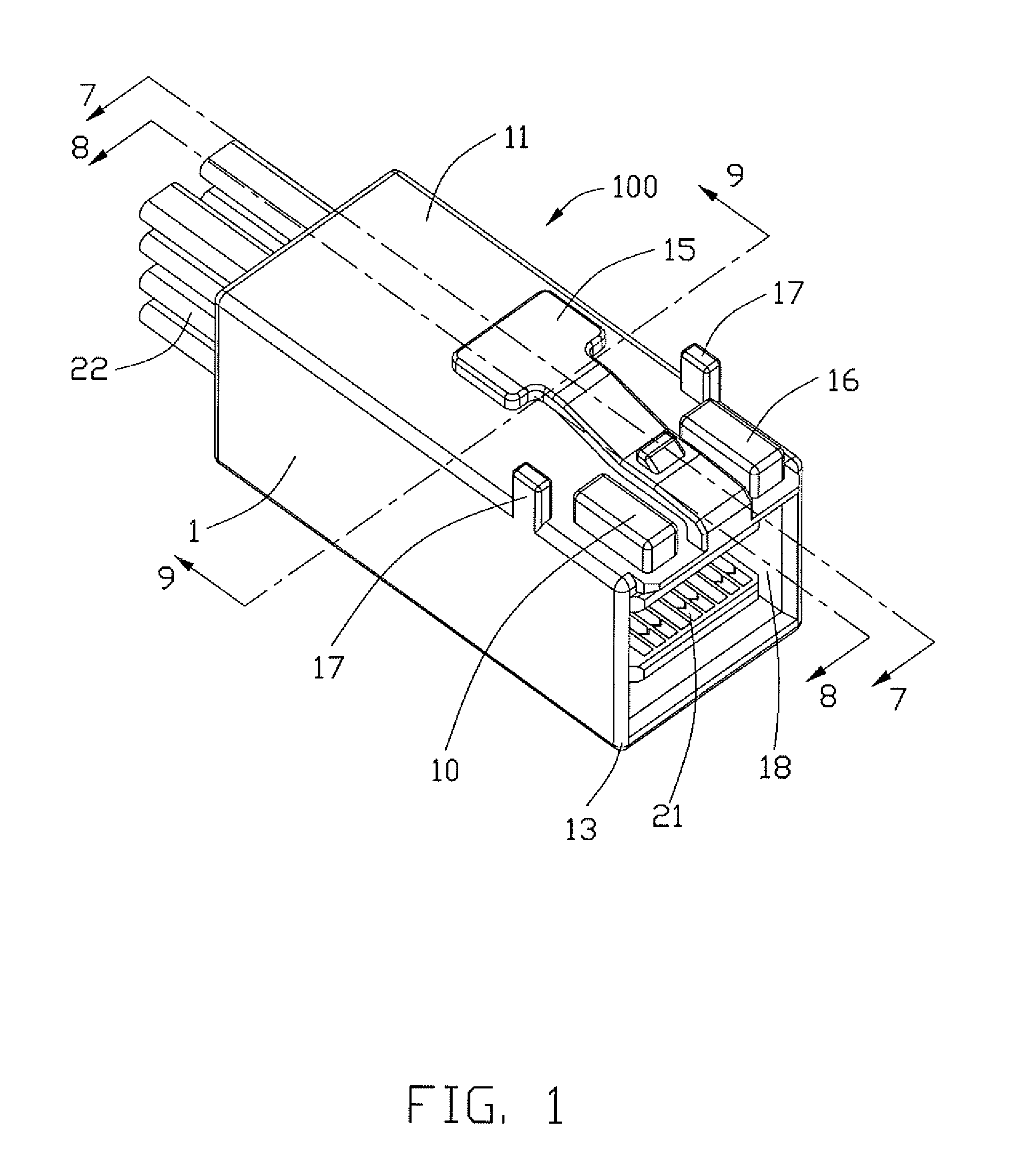
[0018]FIGS. 1 and 2 illustrate perspective views of an electrical connector assembly 100 made in accordance with the present invention. Referring to FIGS. 3 to 6 in conjunction with FIG. 8, the electrical connector assembly 100 comprises a box-shape insulative housing 1, two stacked PCB modules 2 disposed in the insulative housing 1, and a retainer 3 fixing the two PCB modules 2 to the insulative housing 1.

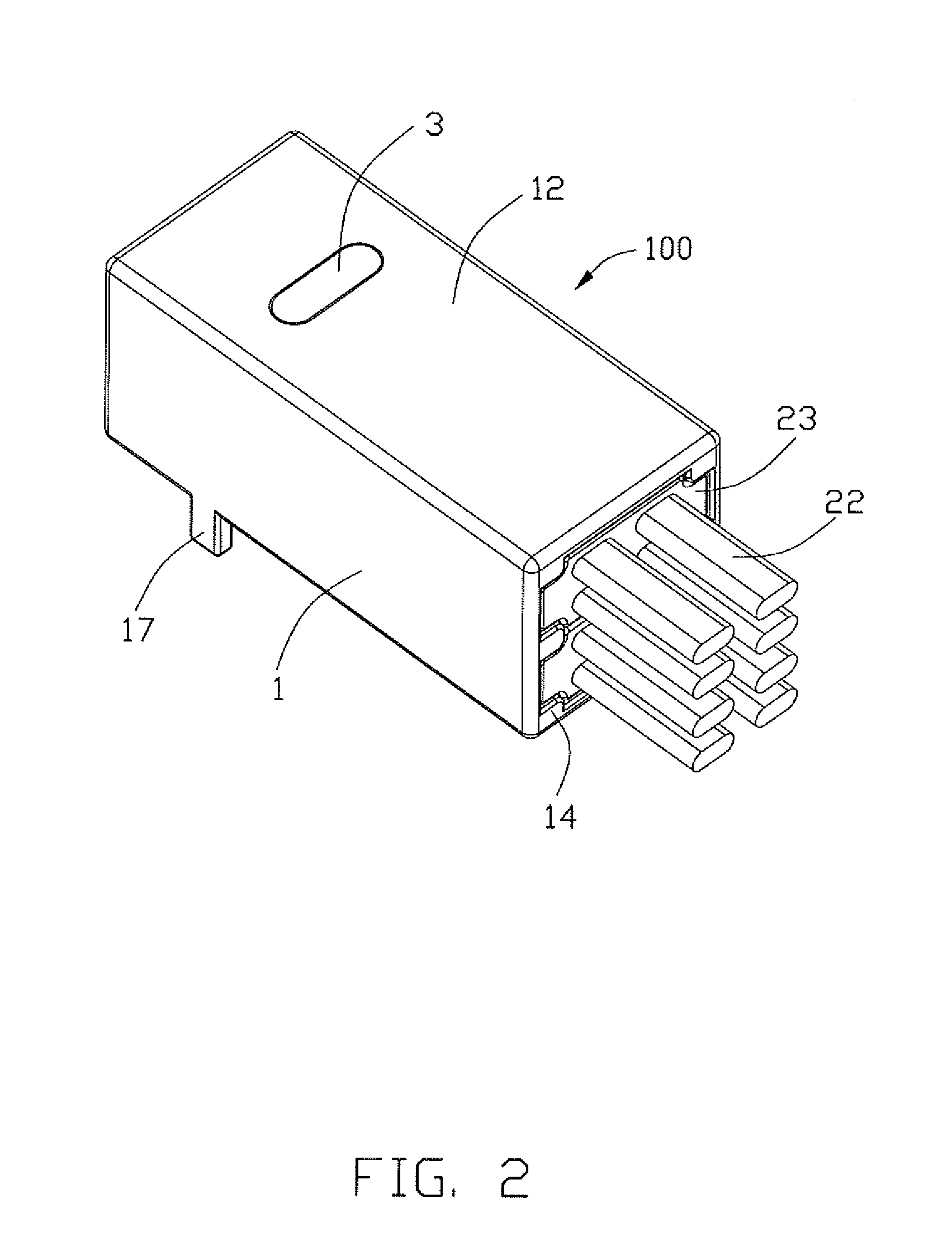
[0019]Referring to FIGS. 1 to 7, the insulative housing 1 defines opposing top surface 11 and bottom surface 12 and opposing front surface 13 and rear surface 14. The insulative housing 1 has a latch mechanism 15 unitary formed on the top surface 11, a pair of projecting portions 16 formed on the top surface 11 and located at two opposite sides of the latch mechanism 15, and a pair of protrusions 17 formed on two sides of the top surface 11 and located rearwardly of the pair of proj...


PUM


Abstract

An electrical connector assembly comprises: an insulative housing defining a receiving space therein communicated with an exterior along a longitudinal direction. The insulative housing defines a resilient latch mechanism integrally formed on a top surface thereof and a pair of projecting portions located at two opposite sides of the latch mechanism for preventing a rotational movement with respect to a complementary mating connector. Two printed circuit board (PCB) modules are arranged in substantially a stacked manner and received into the receiving space. And, a retainer fixes the two PCB modules to the insulative housing.

Description

FIELD OF THE INVENTION[0001]The present invention generally relates to connectors suitable for transmitting data, more specifically to input / output (I / O) connectors with high-density configuration and high data transmitting rate.DESCRIPTION OF PRIOR ART[0002]Communication devices, such as severs, routers, etc., have a development trend toward miniaturization. Thus, the internal room of a communication device will be getting smaller. Generally, traditional I / O connector has a large width. These I / O connectors disposed on a printed circuit board (PCB) card of the communication device will occupy more space such that the number of I / O connectors that may be disposed on the PCB card will be decreased.[0003]Additionally, Mini SAS connectors are widely used in servers. U.S. Pat. No. 7,303,438 issued to Dawiedczyk et al. on Dec. 4, 2007 discloses a Mini SAS connector comprising an insulative housing with a metallic latch assembled to a top surface thereof, a printed circuit board disposed ...

Claims


Application Information

Patent Timeline
Patent Type & Authority Patents(United States)
IPC IPC(8): H01R13/62
CPCH01R9/2408H01R13/6272H01R13/6658H01R24/60H01R2107/00
Inventor WU, JERRY
Owner HON HAI PRECISION IND CO LTD
Why Eureka
Try Eureka