Electrical connector assembly having engaging means for providing holding force

a technology of electrical connectors and components, applied in the direction of coupling device connections, coupling protective earth/shielding arrangements, coupling parts engagement/disengagement, etc., can solve problems such as signal degradation, and affecting the electrical separation

Active Publication Date: 2012-01-19
HON HAI PRECISION IND CO LTD
View PDF0 Cites 19 Cited by
  • Summary
  • Abstract
  • Description
  • Claims
  • Application Information

AI Technical Summary

Benefits of technology

[0001]The present invention generally relates to connectors suitable for transmitting data, more specifically to input / output (I / O) connectors with high-density configuration and high data transmitting rate.

Problems solved by technology

For I / O connectors using in data communication, these desires create somewhat of a problem.
Making the connector smaller (e.g., making the terminal arrangement more dense), however, brings the terminals closer together and tends to decrease the electrical separation, which may lead to signal degradation.
Additionally, there is a desire to increase the density of I / O plug-style connectors and this is difficult to do without increasing the width of the connectors.
Increasing the width of the plug connectors leads to difficulty in fitting the plug into standard width routers and / or servers, and would require a user to purchase non-standard equipment to accommodate the wider plug converters.
As with any connector, it is desirable to provide a reliable latching mechanism to latch the plug connector to an external housing to maintain the mated plug and receptacle connectors together modifying the size and / or configuration the connector housing may result in a poor support for a latching mechanism.
The I / O connector further has metallic holder holding the housing and the strain relief However, the holding force from metallic holder is not enough to hold the housing and strain relief

Method used


Image

  • Electrical connector assembly having engaging means for providing holding force
  • Electrical connector assembly having engaging means for providing holding force
  • Electrical connector assembly having engaging means for providing holding force

Examples


Embodiment Construction

[0023]Reference will now be made to the drawing figures to describe the present invention in detail.

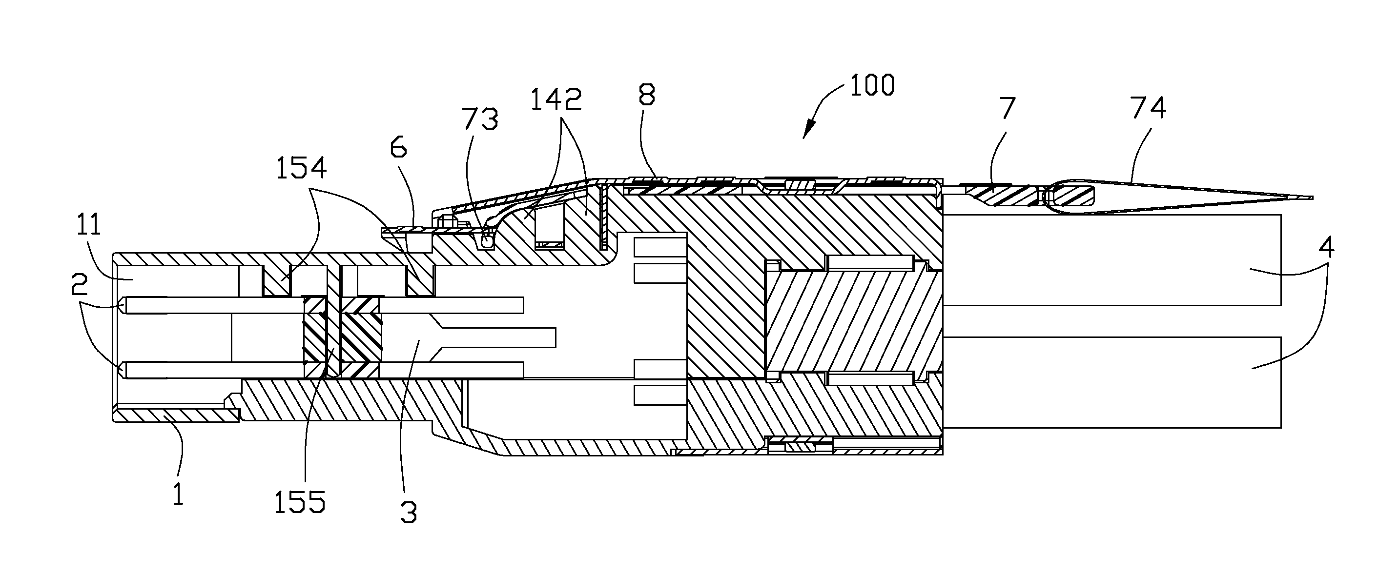
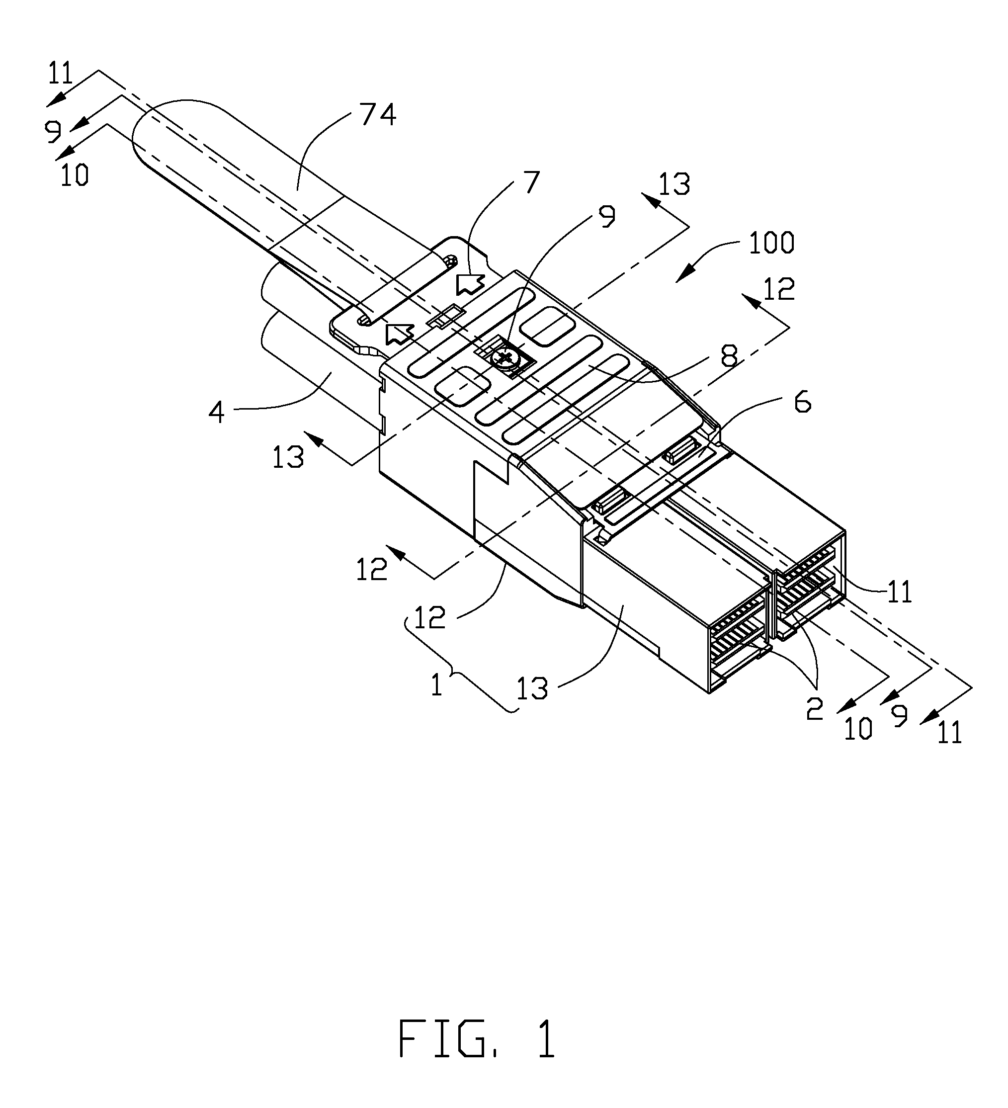
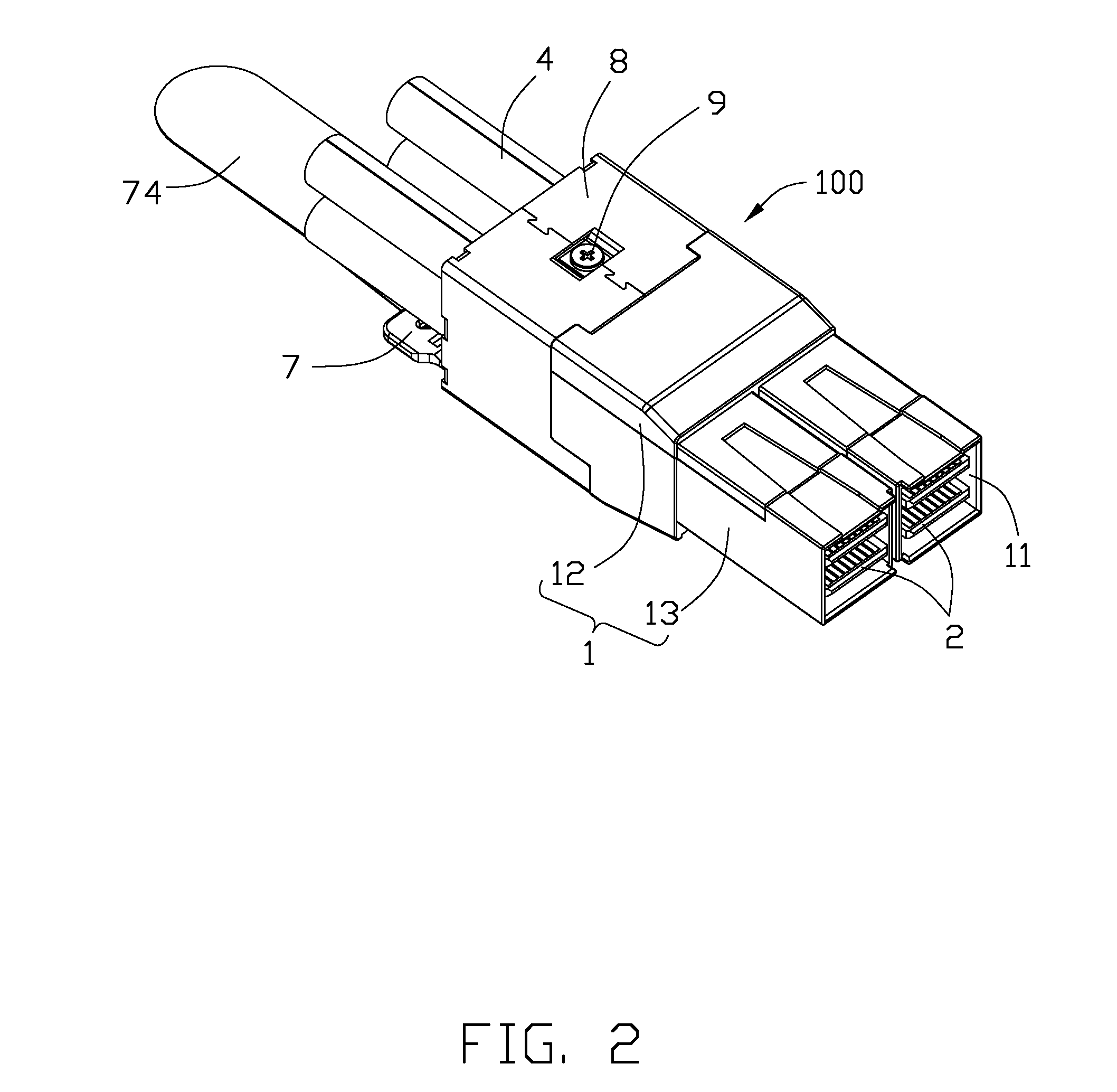
[0024]FIGS. 1 to 3 illustrate perspective views of an electrical connector assembly 100 made in accordance with a first embodiment of the present invention. And referring to FIGS. 4, 5, 11 and 13, the electrical connector assembly 100 comprises a housing 1 having two receiving rooms 11 formed therein and spaced apart with each other. Four printed circuit boards (PCBs) 2 are disposed in the housing 1. And, each of two printed circuit boards (PCBs) 2 are received into a receiving room 11 of the housing 1. Two spacers 2 are disposed in the housing 1. Each of spacer 2 is received into a corresponding receiving room 11 and sandwiched by two PCBs 2. Four cables 4 are respectively electrically connected with four printed circuit boards 2. A strain relief 5 is disposed in the housing 1. Engaging means 9 are assembled to the housing 1 along a vertical direction and interconnected the strain re...


PUM


Abstract

An electrical connector assembly (100), comprises: a housing (1) comprising a first shield part (15), a second shield part (16) assembled with each other; at least one printed circuit board (2) disposed in the housing; a strain relief (5) disposed in the housing and sandwiched by the first shield part and the second shield part; a metallic holder (8) surrounding the housing and binding the first shield part and the second shield part; and a pair of screws (9) respectively assembled to the housing along opposite directions and interlocking the first shield part, the second shield part, the strain relief and the metallic holder together.

Description

FIELD OF THE INVENTION[0001]The present invention generally relates to connectors suitable for transmitting data, more specifically to input / output (I / O) connectors with high-density configuration and high data transmitting rate.Description of Prior Art[0002]One aspect that has been relatively constant in recent communication development is a desire to increase performance. Similarly, there has been constant desire to make things more compact (e.g., to increase density). For I / O connectors using in data communication, these desires create somewhat of a problem. Using higher frequencies (which are helpful to increase data rates) requires good electrical separation between signal terminals in a connector (so as to minimize cross-talk, for example). Making the connector smaller (e.g., making the terminal arrangement more dense), however, brings the terminals closer together and tends to decrease the electrical separation, which may lead to signal degradation.[0003]In addition to the de...

Claims


Application Information

Patent Timeline
Patent Type & Authority Applications(United States)
IPC IPC(8): H01R13/62H01R13/58
CPCH01R13/512H01R13/659H01R13/6275H01R13/5825
Inventor WU, JERRY
Owner HON HAI PRECISION IND CO LTD
Why Eureka
Try Eureka