Electrical connector assembly

a technology of electrical connectors and assembly parts, applied in the direction of coupling device connections, coupling parts engagement/disengagement, electrical apparatus, etc., can solve the problems of signal degradation, decrease the electrical separation, and somewhat of a problem, and achieve high data transmitting rate, easy mating, and high density configuration

Active Publication Date: 2012-04-10
HON HAI PRECISION IND CO LTD
View PDF6 Cites 14 Cited by
  • Summary
  • Abstract
  • Description
  • Claims
  • Application Information

AI Technical Summary

Benefits of technology

[0006]Accordingly, an object of the present invention is to provide an electrical connector assembly with high-density configuration and high data transmitting rate, and easily mating to and discrete from a complementary connector.

Problems solved by technology

For I / O connectors using in data communication, these desires create somewhat of a problem.
Making the connector smaller (e.g., making the terminal arrangement more dense), however, brings the terminals closer together and tends to decrease the electrical separation, which may lead to signal degradation.
Additionally, there is a desire to increase the density of I / O plug-style connectors and this is difficult to do without increasing the width of the connectors.
Increasing the width of the plug connectors leads to difficulty in fitting the plug into standard width routers and / or servers, and would require a user to purchase non-standard equipment to accommodate the wider plug converters.
As with any connector, it is desirable to provide a reliable latching mechanism to latch the plug connector to an external housing to maintain the mated plug and receptacle connectors together modifying the size and / or configuration the connector housing may result in a poor support for a latching mechanism.

Method used


Image

  • Electrical connector assembly
  • Electrical connector assembly
  • Electrical connector assembly

Examples


Embodiment Construction

[0020]Reference will now be made to the drawing figures to describe the present invention in detail.

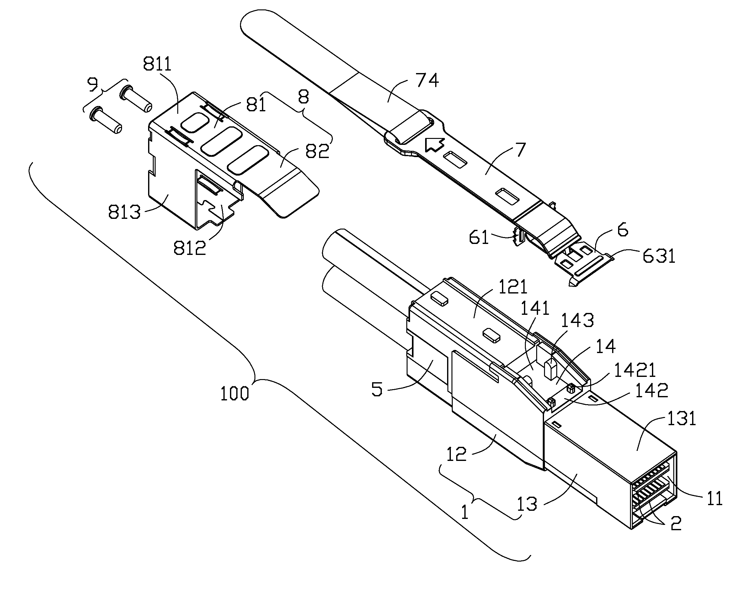
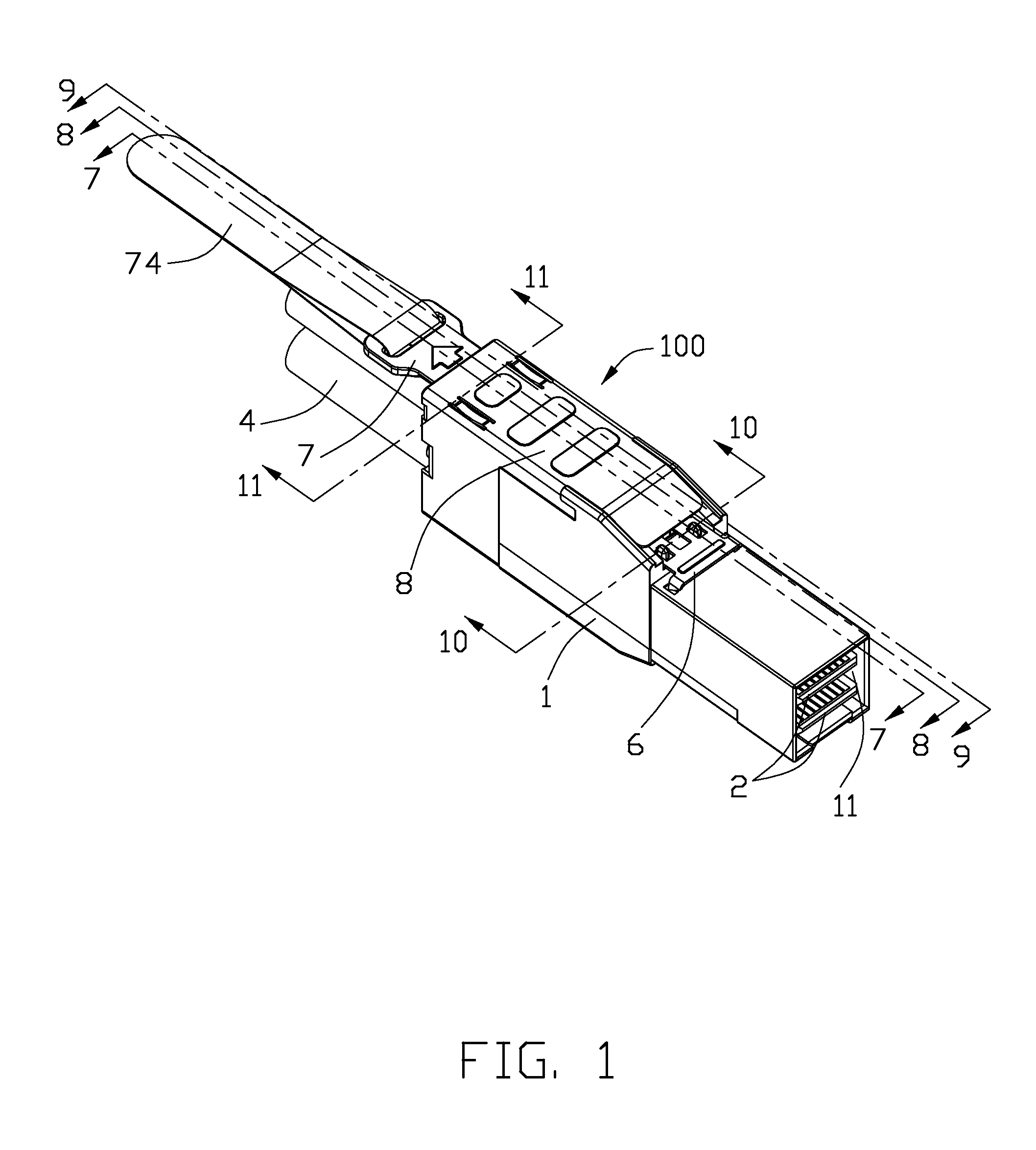
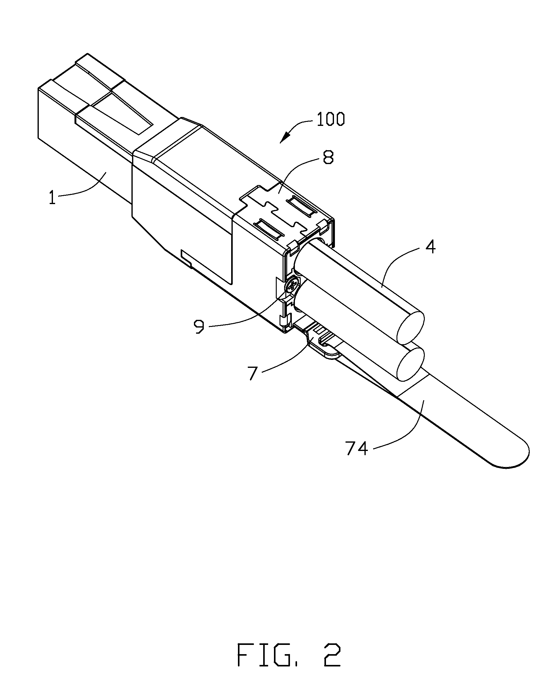
[0021]FIGS. 1 to 4 illustrate perspective views of an electrical connector assembly 100 made in accordance with the present invention. And in conjunction with FIG. 9, the electrical connector assembly 100 comprises a housing 1 having a receiving room 11 therein, two paralleled printed circuit boards (PCBs) 2 disposed in the receiving room 11, a spacer 3 disposed between the two printed circuits boards 2 and positioned with the housing 1, two cables 4 respectively electrically connected with a printed circuit board 2 and a strain relief 5 disposed in the housing 1 and spaced apart with the two cables 4. The electrical connector assembly 100 further comprises a latch mechanism assembled to a top surface of the housing 1 and a metallic holder 8 surrounding a portion of the housing 1 and the latch mechanism. The latch mechanism comprises a latching member 6 and a pulling member 7 intercon...


PUM


Abstract

An electrical connector assembly (100), comprises: a housing (1) having a receiving room (11) therein communicated with an exterior along a longitudinal direction and defining a receiving cavity (14) formed on a top surface thereof. A pair of supporting posts (143) are formed in the receiving cavity. Two paralleled printed circuit boards (2) are received into the receiving room and positioned in the housing. A latching member (6) is located in the receiving cavity and engaged with the housing. A pulling member (7) is supported by the top surface of the housing and having a front portion extending into the receiving cavity and interconnected with the latching member. The pulling member defines a curving portion (722) supported by the pair of supporting posts.

Description

FIELD OF THE INVENTION[0001]The present invention generally relates to connectors suitable for transmitting data, more specifically to input / output (I / O) connectors with high-density configuration and high data transmitting rate.DESCRIPTION OF PRIOR ART[0002]One aspect that has been relatively constant in recent communication development is a desire to increase performance. Similarly, there has been constant desire to make things more compact (e.g., to increase density). For I / O connectors using in data communication, these desires create somewhat of a problem. Using higher frequencies (which are helpful to increase data rates) requires good electrical separation between signal terminals in a connector (so as to minimize cross-talk, for example). Making the connector smaller (e.g., making the terminal arrangement more dense), however, brings the terminals closer together and tends to decrease the electrical separation, which may lead to signal degradation.[0003]In addition to the de...

Claims


Application Information

Patent Timeline
Patent Type & Authority Patents(United States)
IPC IPC(8): H01R13/62
CPCH01R13/5812H01R13/6581H01R13/6335H01R13/6275
Inventor WU, JERRY
Owner HON HAI PRECISION IND CO LTD
Why Eureka
Try Eureka