Middle ear prosthesis having discrete projections for purposes of ossicular attachment

a technology of ossicular attachment and projection, which is applied in the field of middle ear prosthesis, can solve the problems of not effectively transmitting ossicular motion to the fluids of the inner ear, hearing loss, and often dysfunction, and achieves the effects of reducing the chance of necrosis, broad contact, and minimizing disturbance to the underlying mucosa and blood vessels

Inactive Publication Date: 2014-09-16
SCHEURER MARK MATTHEW
View PDF8 Cites 0 Cited by
  • Summary
  • Abstract
  • Description
  • Claims
  • Application Information

AI Technical Summary

Benefits of technology

[0008]The present invention relates to the concept that if a relatively large patch or area of contact between an ossicular prosthesis and an ossicle can be avoided, then disturbance to the underlying mucosa and blood vessels can be minimized with a reduction in the chance for necrosis. More particularly, broad contact may be minimized by a design in which discrete projections from the prosthesis' ossicle interface surface space that surface away from the bone. Moreover, a very secure attachment between the ossicle and the prosthesis can be anticipated, due to the resistance to motion engendered by the partial embedment of these projections in the ossicle. A more secure attachment can be anticipated to reduce the chance of prosthesis translocation following surgery, which can cause surgical failure even in the absence of ossicular necrosis.
[0011]The projections are inherently designed to minimize the surface area of prosthesis to ossicle contact, thereby minimizing the potentially damaging effect that broader contact may have, as described in “Background of the Invention.” They also have the advantage of attaching firmly to the ossicle via embedment of said projections which is anticipated to reduce the risk of surgical failure further by reducing the risk the prosthesis will move away from its position at the time of surgical implantation.
[0012]In one embodiment, the projections are envisioned as having sharp ends which could enhance firm embedment in the ossicular bone to which they are in contact, creating a secure attachment without a significant amount of total contact between the prosthesis and the ossicle.

Problems solved by technology

In the case of the stapes, dysfunction often occurs as a result of a disease process called otosclerosis in which the footplate of the stapes becomes fused to the surrounding bone and no longer effectively transmits ossicular motion to the fluids of the inner ear.
This bone loss in the area of the prosthesis attachment can cause loosening of the prosthesis and resultant hearing loss because of piston migration out of the hole in the stapes footplate and / or de-coupling of the motion from the incus to the prosthesis.
Bone / tissue loss in the area of the attachment of the stapes prosthesis to the incus is thought to be due to impaired blood supply to the long process of the incus after surgery.
It is widely believed that a prosthesis which exerts sufficient mechanical pressure on blood vessels / mucosa near the surface of the incus can cause a restriction of blood flow sufficient to cause incus necrosis and subsequent failure of the prosthesis.
Since the blood supply in the area of the prosthesis attachment is tenuous after surgery and most prostheses have areas of very broad or circumferential contact points with the long process, relatively large areas where blood vessels or delicate mucosa are located can be compressed by the prosthesis and cause death of the underlying or distal tissues.
Nevertheless, all efforts to date share the common characteristic that at least some of the wire or ribbon is broadly in contact with the incus and consequently have the potential to cause pressure necrosis to the underlying mucosa and loss of bone in these areas of broad contact.
Commonly, the prosthesis “falls over” after surgery with a loss of contact with the malleus, with resultant hearing loss.

Method used


Image

  • Middle ear prosthesis having discrete projections for purposes of ossicular attachment
  • Middle ear prosthesis having discrete projections for purposes of ossicular attachment
  • Middle ear prosthesis having discrete projections for purposes of ossicular attachment

Examples


Embodiment Construction

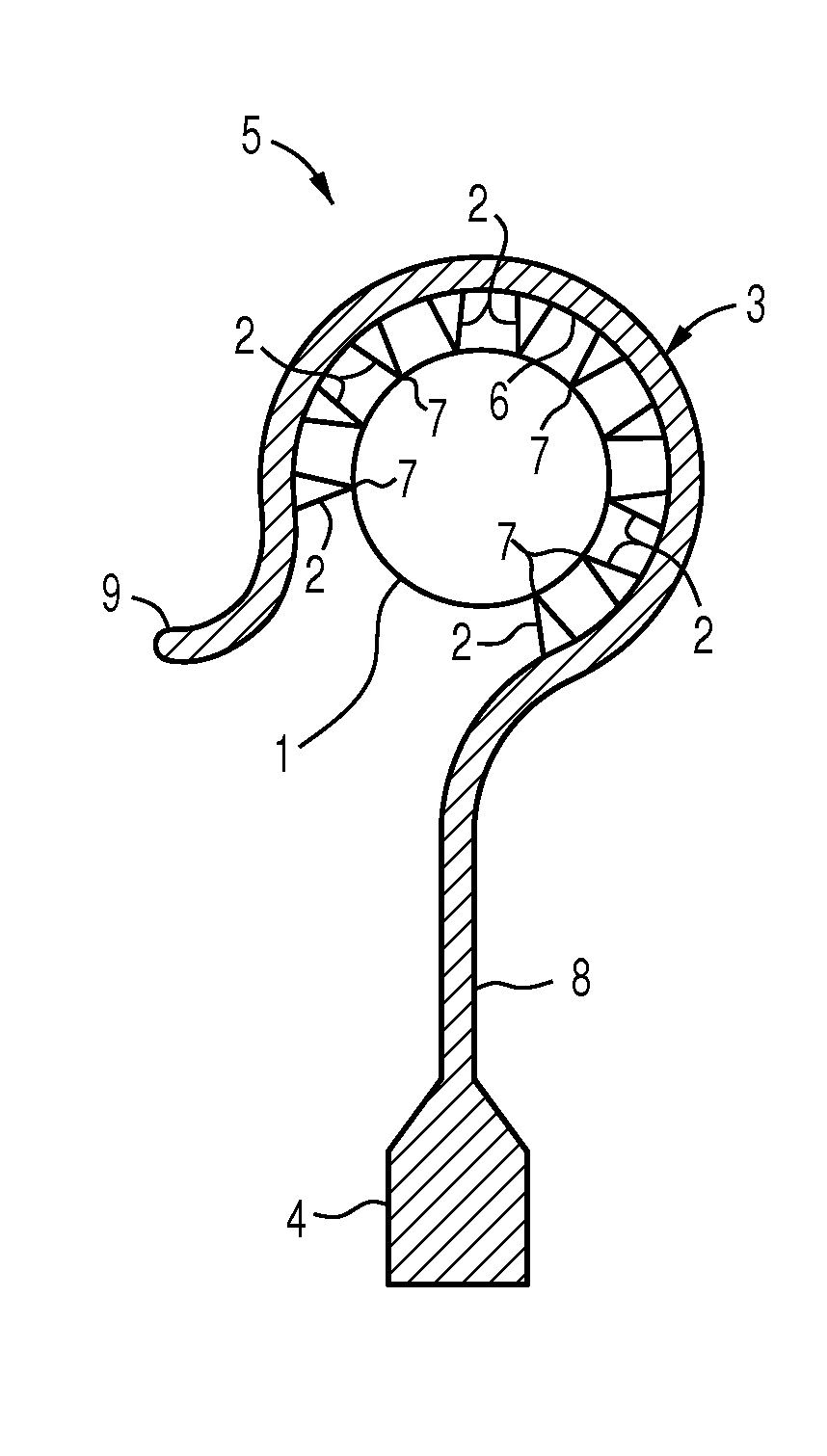
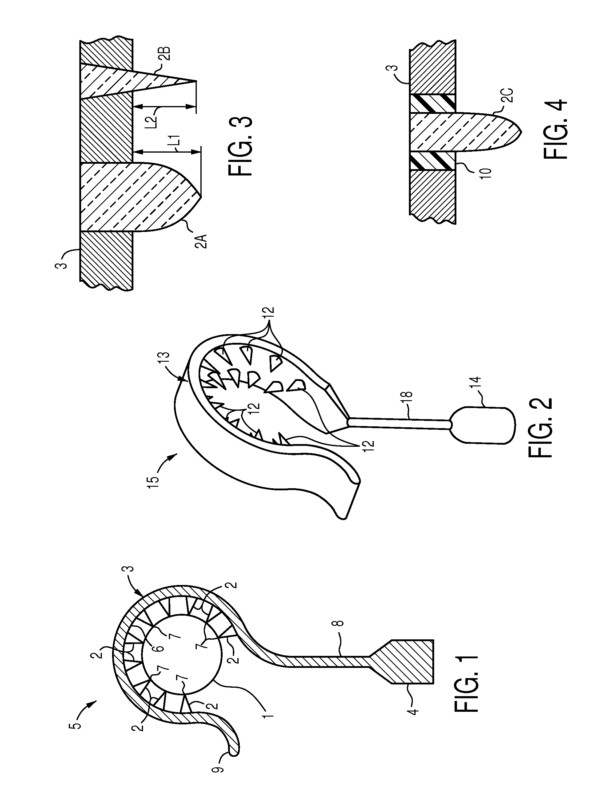
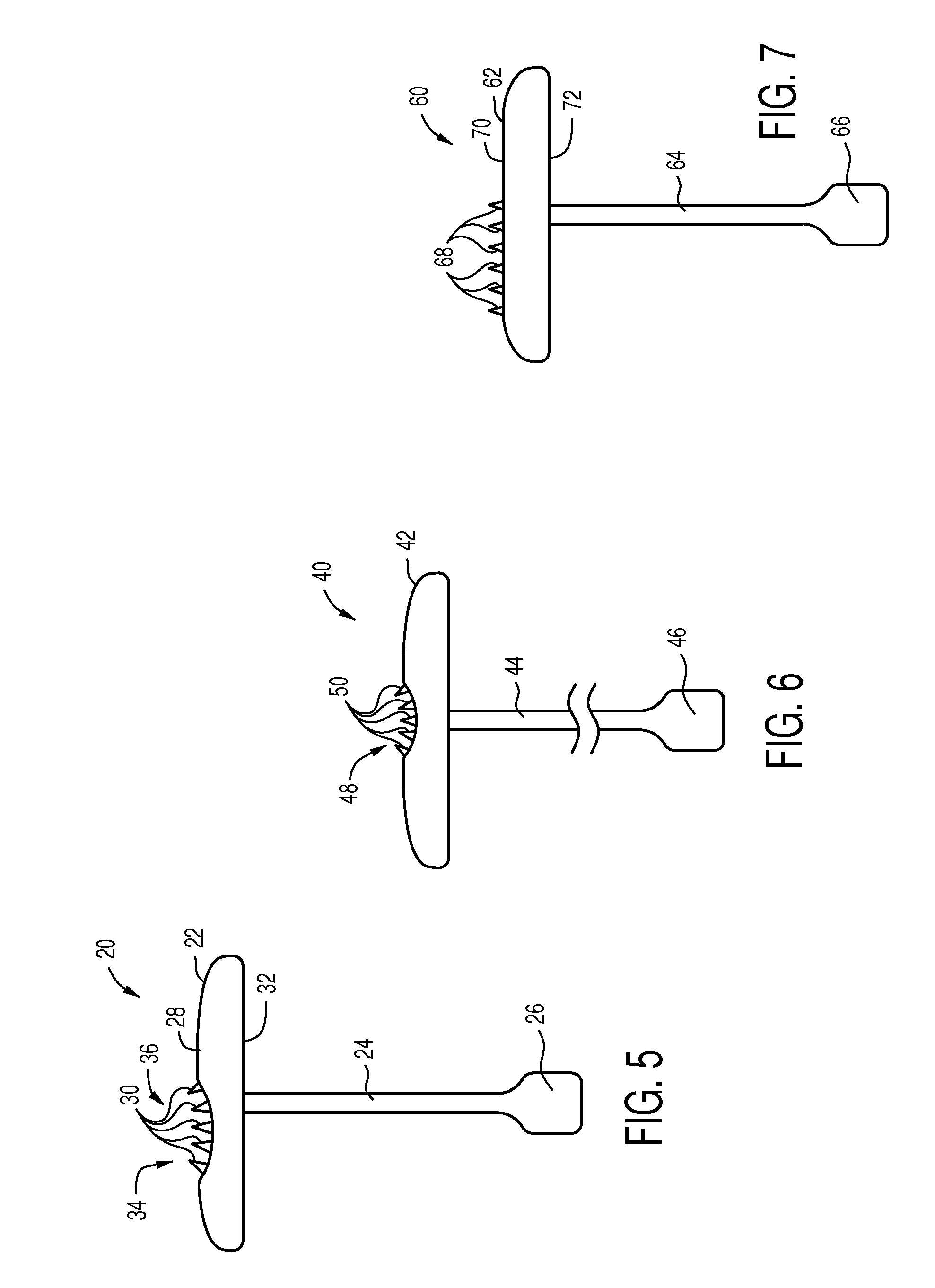
[0022]FIG. 1 shows a middle ear prosthesis such as a stapes prosthesis 5 comprising a loop 3 which is formed as a partial circle of at least one hundred eighty degrees, or as shown, three hundred to three hundred thirty degrees, for encircling an ossicle such as an incus 1 (seen in cross section in FIG. 1). It would of course be possible to arrange the loop 3 as a full circle, by adding an element which closes the gap which exists when the loop 3 forms a partial circle as depicted and a suitable fastener for retaining the added element to the loop 3 (this option is not shown). The loop 3 bears a linear array of projections or spikes 2, which may for example be arrayed as a row of spikes 2, which project inwardly from the inner surface 6 of the loop 3, and which make contact with the underlying incus 1. The terms projection and spike, both in the singular and in the plural, will be used interchangeably herein. Inwardly signifies towards the center of the circle which would exist if t...


PUM

PropertyMeasurementUnit
angleaaaaaaaaaa
lengthaaaaaaaaaa
surface areaaaaaaaaaaa

Abstract

A middle ear ossicle prosthesis in which the component for ossicular attachment comprises a surface bearing a plurality of discrete projections facing the ossicle to which it is attached which minimize total contact between the prosthesis and the ossicle. The prosthesis may comprise a loop forming a partial circle for encircling an ossicle, a piston for transmitting vibrations from the loop to the inner ear, and a rod solidly connecting the loop to the piston. The loop may have an upwardly turned end to facilitate placement of the loop over the ossicle. The projections may be provided in one row, two rows, or may be otherwise arrayed, and may be dissimilar from one another in configuration and dimensions.

Description

CROSS-REFERENCE TO RELATED APPLICATION[0001]This application claims priority benefit of Application No. 61 / 529,590, filed Aug. 31, 2011.BACKGROUND OF INVENTION[0002]Numerous prior designs of ossicular prostheses have sought to establish functional continuity of the ossicular chain after damage to some or all of the ossicles secondary to disease or congenital anomaly. Frequently, when the stapes is damaged or diseased, re-establishment of a connection to the inner ear via stapedectomy or stapedotomy is also required. Prostheses most often are designed to attach to remaining healthy ossicles and replace the function of the ossicle(s) which are missing or diseased.[0003]In the case of the stapes, dysfunction often occurs as a result of a disease process called otosclerosis in which the footplate of the stapes becomes fused to the surrounding bone and no longer effectively transmits ossicular motion to the fluids of the inner ear. Most stapes prostheses over the last several decades hav...

Claims


Application Information

Patent Timeline
Patent Type & Authority Patents(United States)
IPC IPC(8): A61F2/18
CPCA61F2/18A61F2002/183A61F2220/0016A61F2210/0004A61F2210/0014A61F2230/0006A61F2230/0045A61F2230/0065A61F2230/0067A61F2230/0086A61F2250/0026A61F2250/0031A61F2250/0051
Inventor SCHEURER, MARK, MATTHEW
Owner SCHEURER MARK MATTHEW
Why Eureka
Try Eureka