Push button structure

a button and button technology, applied in the direction of emergency actuators, electrical devices, electric switches, etc., can solve the problem of bad button operation feeling, and achieve the effect of improving the button operation feeling

Inactive Publication Date: 2014-09-16
MITSUBISHI ELECTRIC CORP
View PDF19 Cites 49 Cited by
  • Summary
  • Abstract
  • Description
  • Claims
  • Application Information

AI Technical Summary

Benefits of technology

[0006]The present invention has been made to solve the above-mentioned problems, and an object of the invention is to provide a push button structure having an improved operational feeling of a button.
[0008]According to an aspect of embodiments of the invention, when the board and the button are attached at an angle to the panel, the direction tangential to the rotational path of the tip of the leg of the button is substantially the same as the stroke direction of the switch; thus, it becomes possible to restrain the tip of the leg from sliding on the switch, thereby providing the push button structure with an improved operational feeling thereof.

Problems solved by technology

Since the conventional push button structure is arranged as described above, the tip of the leg travels on the switch in a sliding manner to push the switch upon depression of the button, so that friction is caused, and / or the rotating button rubs the fringe of a panel opening, resulting in a bad operational feeling of the button, which poses a problem.

Method used


Image

  • Push button structure
  • Push button structure
  • Push button structure

Examples


first embodiment

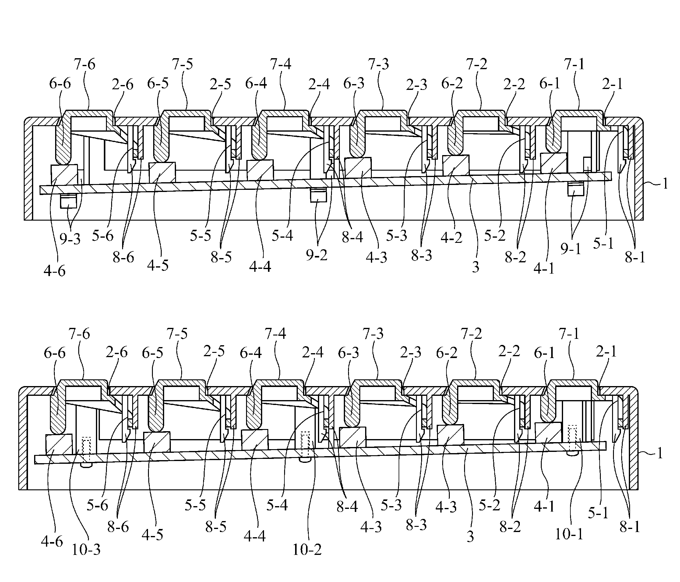
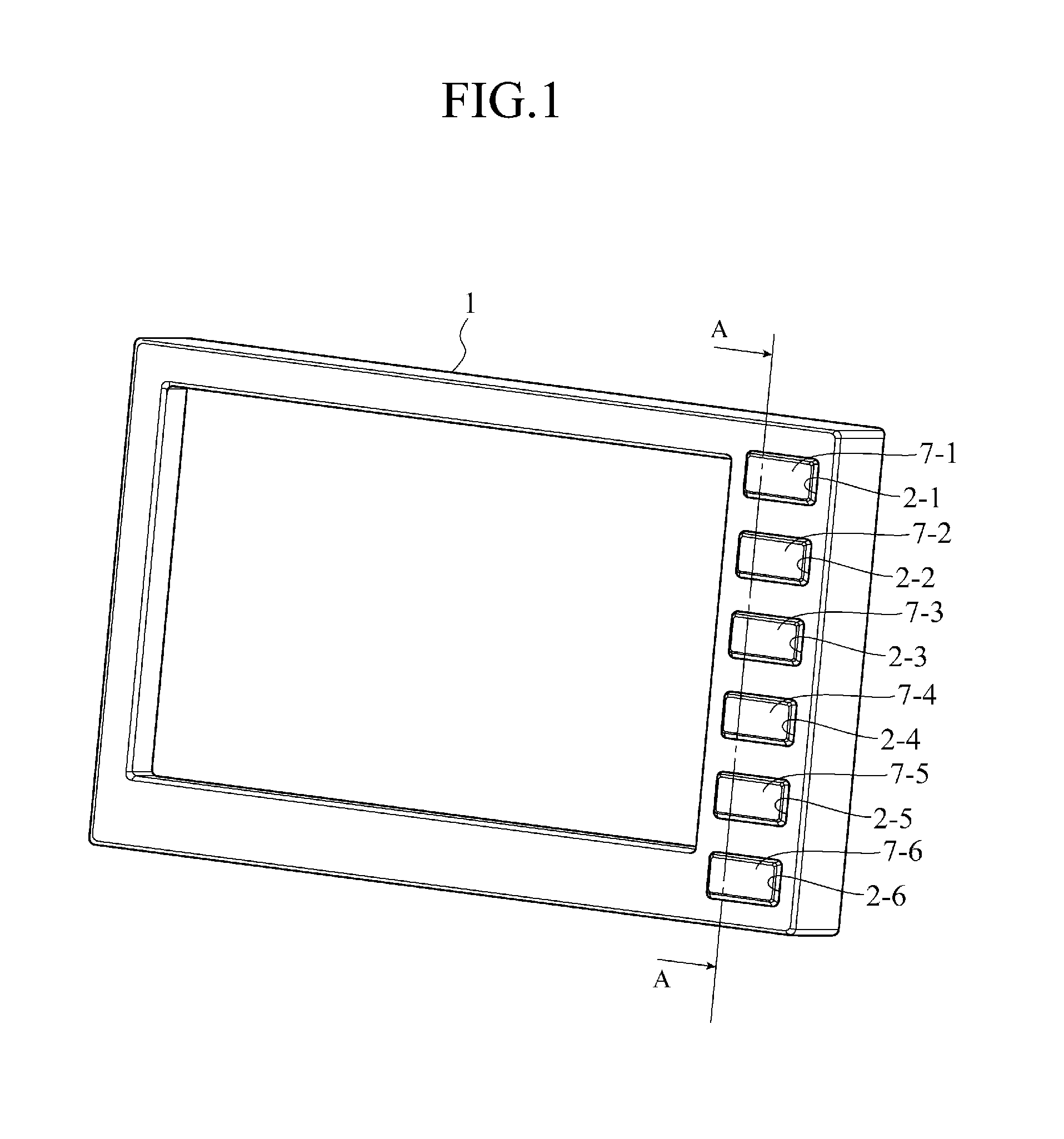
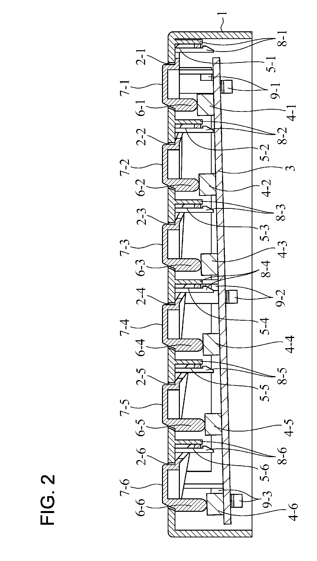
[0016]A constructional example to which a push button structure of a first embodiment in the invention is applied to a panel 1 on the front of an in-vehicle apparatus will be described. As shown in FIG. 1 and FIG. 2, a push button structure includes: the panel 1 in which openings 2-1 to 2-6 for exposing a button are provided; a board 3 attached at an angle to the panel 1; switches 4-1 to 4-6 mounted on a face of the board 3 opposite to the panel 1; and buttons 7-1 to 7-6 for pushing the switches 4-1 to 4-6 with legs 6-1 to 6-6 on the other end side thereof, such that the buttons are rotated about rotational central sections 5-1 to 5-6 on one end side thereof, when the buttons are pushed toward the side of the board 3 with exposed from the openings 2-1 to 2-6 of the panel 1, respectively.

[0017]Hereinafter, when parts common to the openings 2-1 to 2-6 are explained, the openings are simply referred to as an “opening 2” without distinction. Similarly, the switches 4-1 to 4-6 are referr...


PUM


Abstract

A push button structure includes: a panel 1 in which an opening 2 for exposing a button 7 is provided; a button 7 having a leg of which one end side is supported by a rotational central section 5 of the panel 1 and of which the other end side has a leg 6 extending in an orthogonal direction to the panel 1, wherein the other end side is rotated about the rotational central section 5 when the button is pushed with exposed from the opening 2 of the panel 1; and a board 3 on which a switch 4 is mounted and which is attached at an angle to the panel 1 such that a direction C tangential to a rotational path of the leg 6 is substantially the same as a stroke direction D of the switch 4.

Description

TECHNICAL FIELD[0001]The present invention relates to a push button structure provided on a panel of an in-vehicle apparatus and so on.BACKGROUND ART[0002]A conventional push button structure is a structure such that a push button is rotatably supported in an opening of a panel by a hinge section. When the button is pushed, the other end side thereof is rotated about the hinge section side, and a leg protrusively provided on the other side pushes a switch inside a panel. Since the panel to which the button is attached and a board on which the switch is mounted are disposed parallel to each other, the tip of the leg during rotation travels in a sliding manner on the switch. For this reason, when the button is depressed and recovered, friction is caused on the contact surfaces between the leg and the switch, which leads to a bad operational feeling of the button.[0003]Thus, in a push button structure of Patent Document 1, for example, the contact faces between the tip of a leg of a bu...

Claims


Application Information

Patent Timeline
Patent Type & Authority Patents(United States)
IPC IPC(8): H01H13/70H01H21/24
CPCH01H21/24H01H2221/016H01H2221/044
Inventor HIROTA, HIDEYUKI
Owner MITSUBISHI ELECTRIC CORP
Why Eureka
Try Eureka