

Metallic structures having porous regions from imaged bone at pre-defined anatomic locations
a metal structure and pre-defined anatomic location technology, applied in the field of metal structures having porous or mesh regions, can solve the problems unable to adequately replicate the trabecular structure of bone products, and unable to achieve the effect of reducing the density of three-dimensional structural densities
- Summary
- Abstract
- Description
- Claims
- Application Information
AI Technical Summary
Benefits of technology
Problems solved by technology
Method used
Image

Examples
example 1
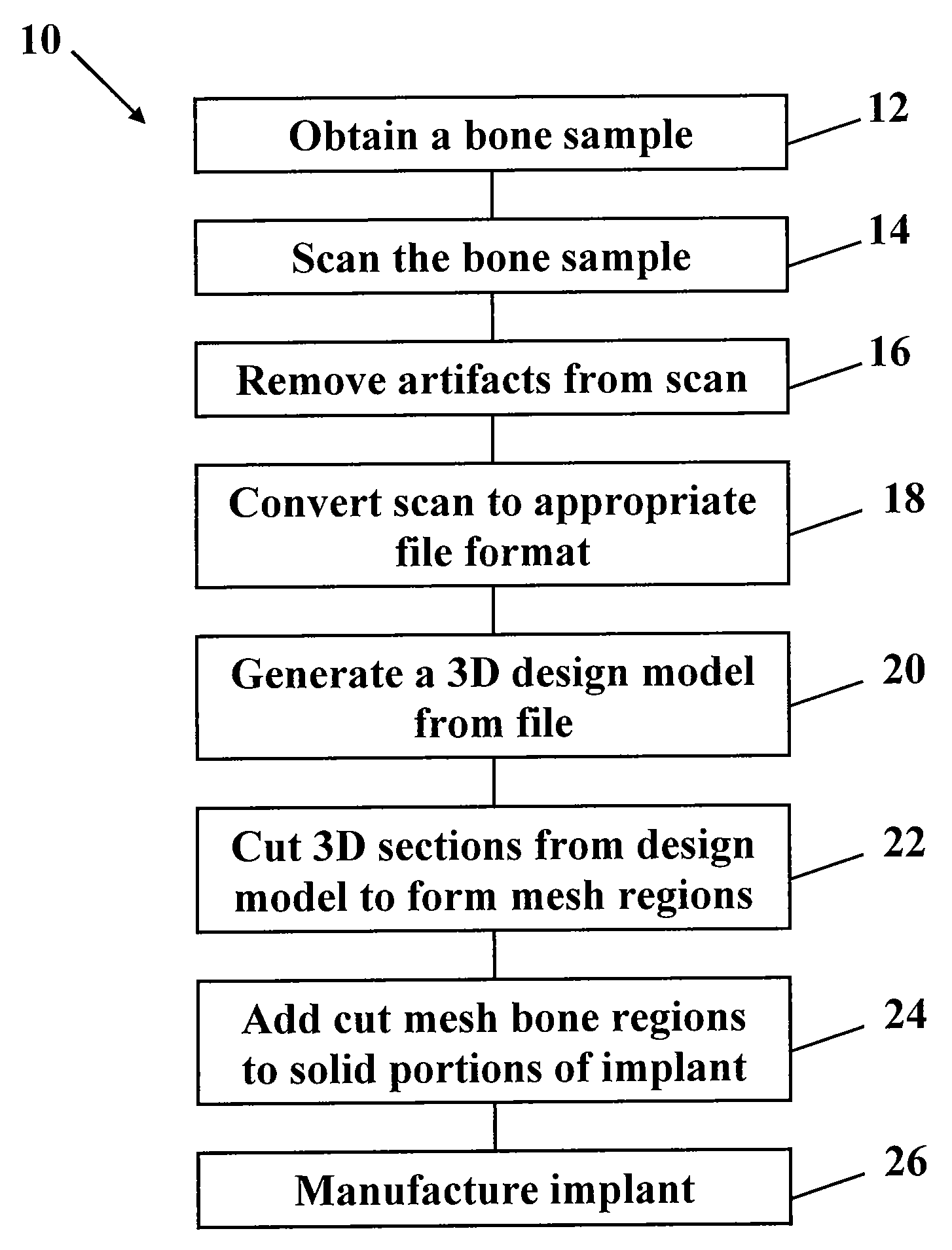
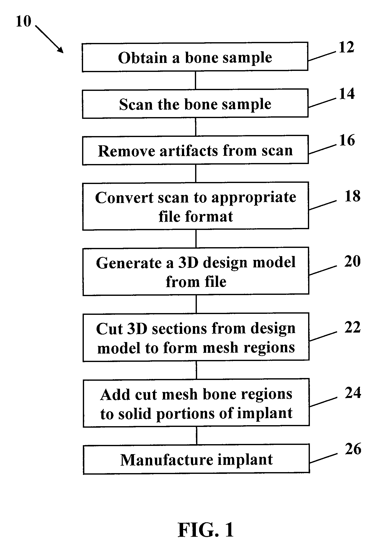
[0036
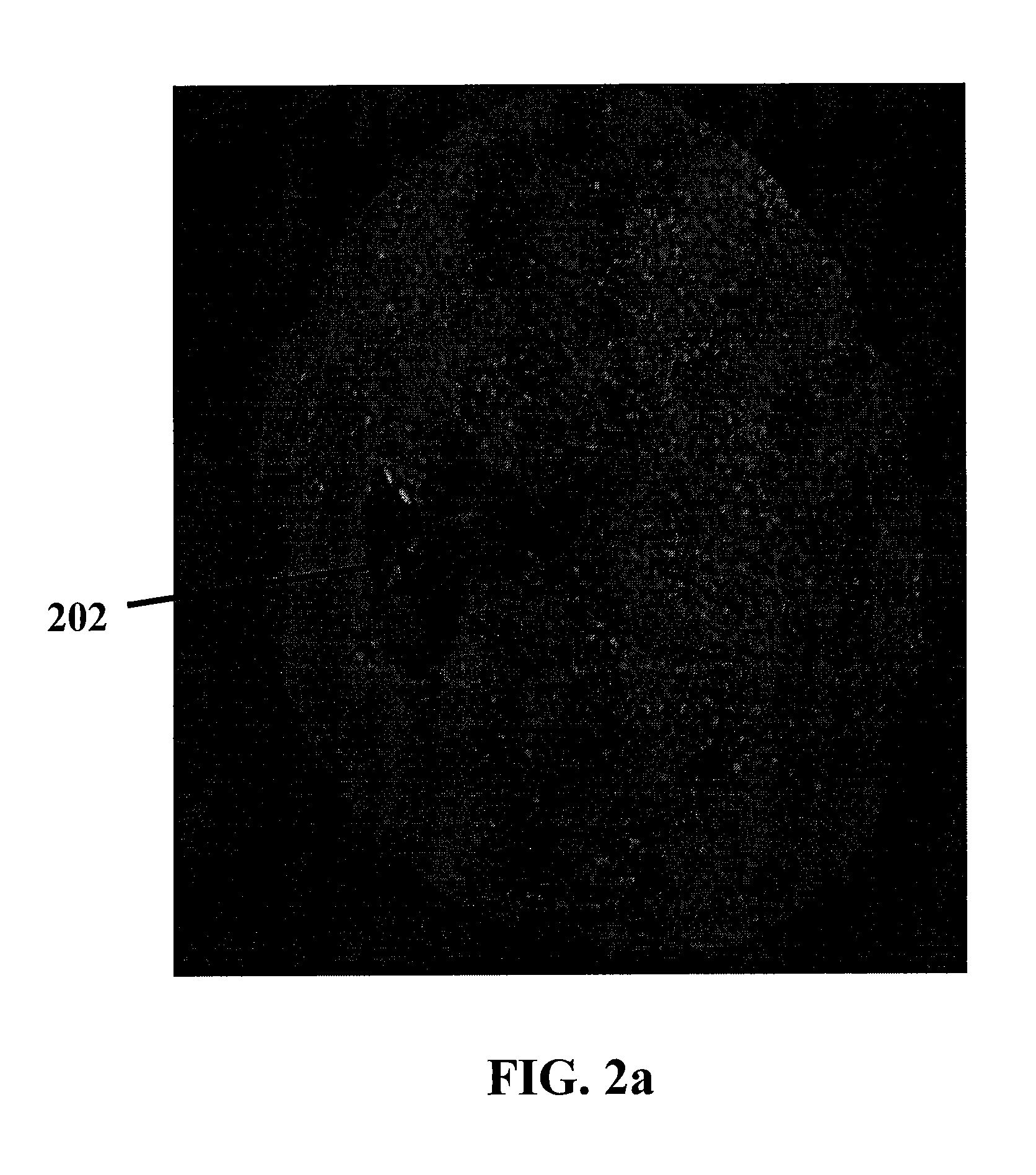
[0037]FIG. 3 depicts an illustrative 3D scan of a trabecular bone obtained from a humeral head in accordance with the techniques of the present invention. In accordance with this illustrative embodiment, bone was selected from a cadaver, sectioned, placed in a tube to scan, and then scanned at a resolution of 40 microns. While this scan was taken at a resolution of 40 microns, those of skill in the art will understand and appreciate that various other scanning resolutions can be utilized if desired. For instance in certain illustrative embodiments, a resolution of about 20 microns can be used.
[0038]FIG. 4 shows cross-sectional view of a mesh wing that was created from a humeral head MicroCT scan in accordance with the teachings of the present invention, while FIG. 5 shows a front, cross-sectional view of a stemless shoulder prosthesis 30 having a pair of illustrative mesh wings 38 (such as the mesh wing shown in FIG. 4) coupled thereto. More specifically, and with particular re...
PUM
| Property | Measurement | Unit |
|---|---|---|
| computed tomography | aaaaa | aaaaa |
| CT | aaaaa | aaaaa |
| size | aaaaa | aaaaa |
Abstract
Description
Claims
Application Information