
Drinking cup with a straw connected to the bottom of the cup

a technology of drinking cups and straws, which is applied in the field of drinking cups, can solve the problems of prone to being lost, easy to fall out of the cup, and difficulty in and achieves the effects of convenient and quick separation, convenient viewing of the level of contents, and convenient sucking the contents of the cup cavity

Active Publication Date: 2014-10-07
OSULLIVAN SEAN PATRICK
View PDF32 Cites 15 Cited by
  • Summary
  • Abstract
  • Description
  • Claims
  • Application Information

AI Technical Summary

Benefits of technology

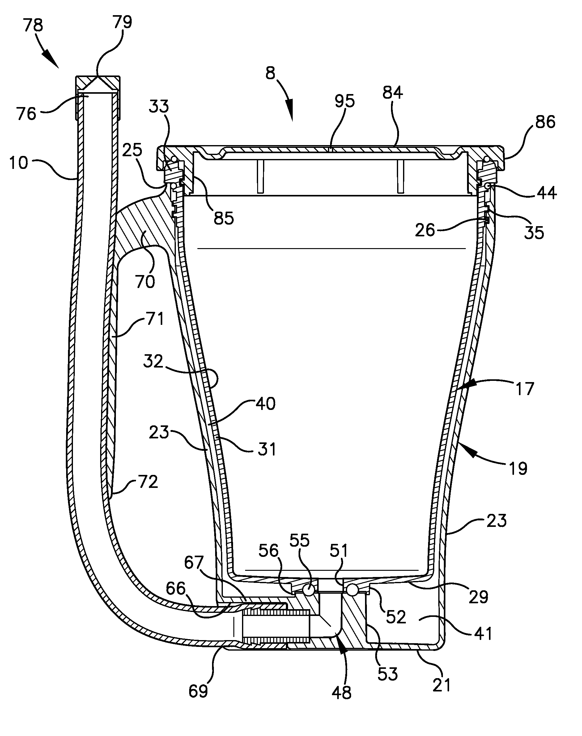
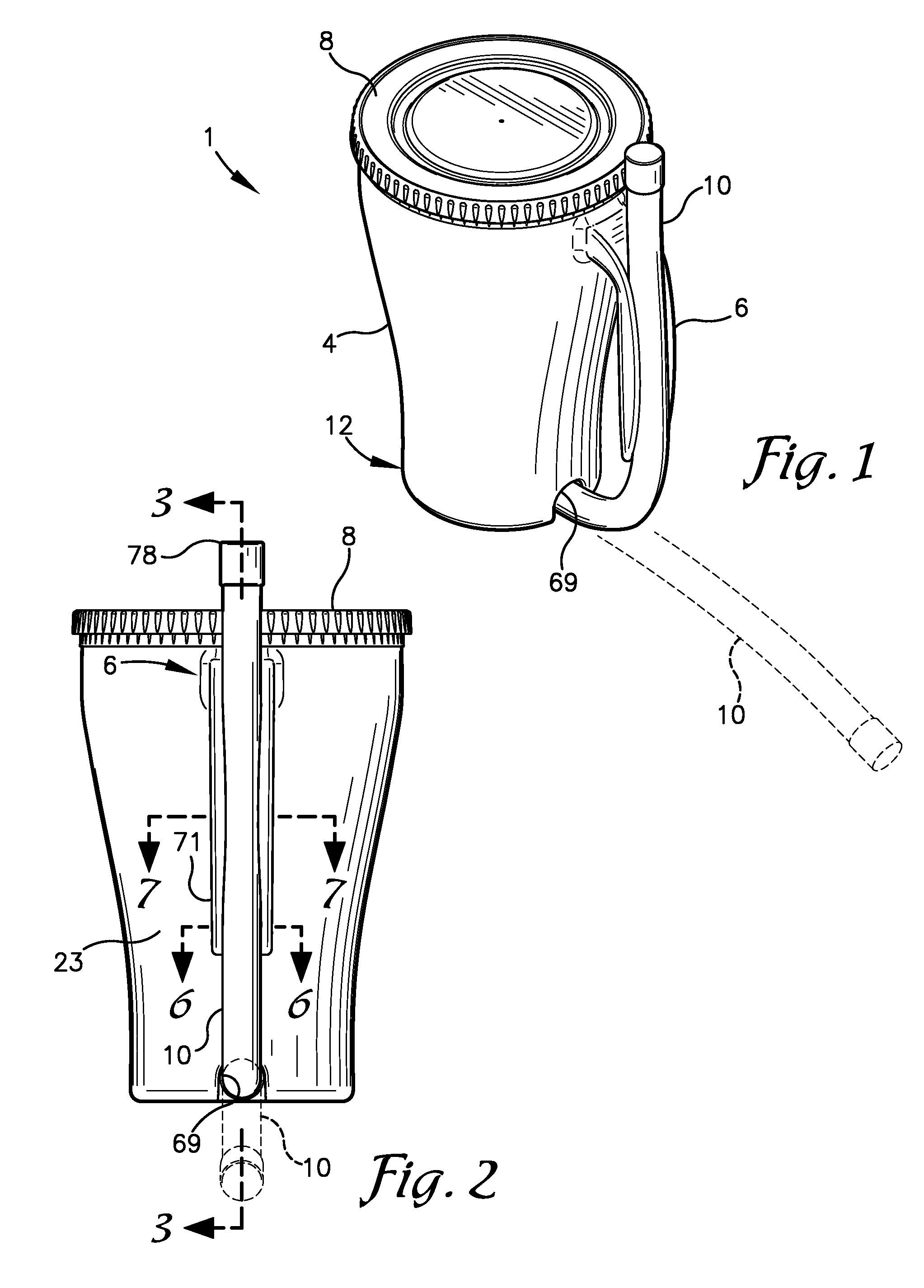
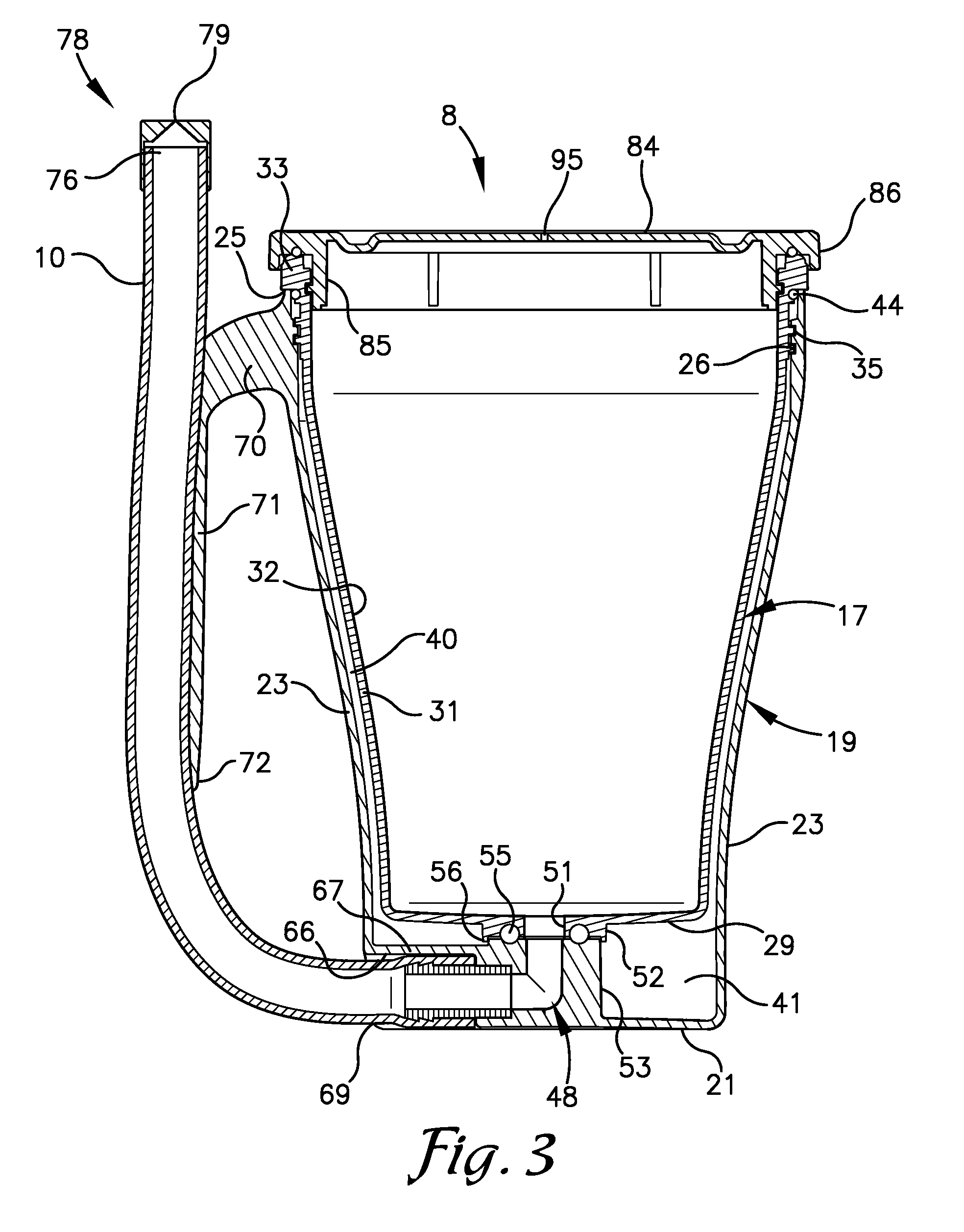
[0009]The present invention comprises a cup from which a person can drink without having to tilt or lower the rim of the cup to mouth level to permit drinking from the cup while in a reclined or supine position. The cup comprises a cup body having a base and a side wall. The side wall extends upward from the base and surrounds an interior cavity for holding liquid. An outlet is formed through the base in flow communication with the interior cavity. A flexible straw is connected to the cup body in flow communication with the interior cavity through the outlet. A handle attached to the cup body is shaped to receive the flexible straw and releasably secure the flexible straw thereto.
[0010]An inner end of the straw is removably secured to a barbed nipple which is flow connected to an outlet passageway formed in the base of the cup. The barb is preferably positioned within a recess formed in the base of the cup to avoid breaking off of the nipple and for a cleaner appearance.
[0012]The cup preferably includes a lid removably securable to an upper end of the body to prevent spilling of the contents. A vent hole is provided in the lid to facilitate sucking the contents of the cup cavity out through the straw. A bite actuated valve is formed in a mouthpiece connected to an outlet end of the flexible straw. The bite actuated mouthpiece is advanceable from a normally closed alignment, preventing liquid from flowing out the outlet end of the flexible straw, to an open alignment when squeezed to allow liquid to flow out the outlet end of the flexible straw.
[0013]The cup body preferably utilizes a double wall configuration and has an inner cup shell and an outer cup shell. The inner cup shell includes a side wall connected to a base, and the side wall extends upwardly from the base to form the cavity for holding liquid. Similarly, the outer cup shell includes a side wall connected to a base, with the side wall extending upward from the base to form a cavity in which the inner cup is received. In addition to the benefit of thermal insulation, the invention's double wall design allows the inner cup to be easily and quickly separated from the outer cup for cleaning. The body may be made from a clear plastic to facilitate viewing of the level of contents thereon or of a sheet with designs, logos or indicia printed thereon positioned between the inner and outer cup side walls.

Problems solved by technology

Drinking from a conventional cup with or without a straw is difficult or impossible to manage for bedbound individuals or other persons incapable of sitting up from a reclining to an upright position.
If such a long straw is not secured to the cup, it would tend to fall out of the cup either while the user is attempting to drink from the cup or when the cup is not in use.
Such a straw would be prone to being lost and it would be difficult difficult to prevent the end of the straw from touching unsanitary surfaces when not in use.
In addition, the length of such a straw, if secured to the cup, would make the cup more difficult to store.
The clasp disclosed by Unkenholz for securing the straw in place is problematic in that it is readily prone to snapping off or breaking, thereby eliminating the means for securing the straw to the body of the cup.
An excessively cold outer wall could lead to condensation on the outside of the cup, thus making the cup slippery or uncomfortable to hold.
However, it was not heretofore known to connect a straw to a double walled cup near the bottom thereof to obtain the benefits of such a bottom draining cup in combination with an insulated cup.

Method used


Image

  • Drinking cup with a straw connected to the bottom of the cup
  • Drinking cup with a straw connected to the bottom of the cup
  • Drinking cup with a straw connected to the bottom of the cup

Examples


Embodiment Construction

[0025]As required, detailed embodiments of the present invention are disclosed herein; however, it is to be understood that the disclosed embodiments are merely exemplary of the invention, which may be embodied in various forms. Therefore, specific structural and functional details disclosed herein are not to be interpreted as limiting, but merely as a basis for the claims and as a representative basis for teaching one skilled in the art to variously employ the present invention in virtually any appropriately detailed structure. The drawings constitute a part of this specification and include exemplary embodiments of the present invention and illustrate various objects and features thereof.

[0026]Certain terminology will be used in the following description for convenience in reference only and will not be limiting. For example, the words “upwardly,”“downwardly,”“rightwardly,” and “leftwardly” will refer to directions in the drawings to which reference is made. The words “inwardly” a...


PUM


Abstract

A drinking cup for use by individuals in reclined position is disclosed. The cup includes a flexible straw attached to the base of the cup, a lid, and a handle with a groove for receiving and storing the straw. A bight actuated mouthpiece valve is connected to the distal end of the straw. The cup may be of double walled construction and the lid includes a small hole to release any vacuum created as a user sucks on the straw.

Description

CROSS-REFERENCE TO RELATED APPLICATIONS[0001]This application is a continuation-in-part of and claims priority from application Ser. No. 29 / 434,291 filed Oct. 11, 2012, which is a continuation-in-part of application Ser. No. 29 / 412,858, filed Feb. 8, 2012, now abandoned. This application claims priority from provisional patent application No. 61 / 640,956 filed May 1, 2012, the contents of which are incorporated herein by reference.BACKGROUND OF THE INVENTION[0002]1. Field of the Invention[0003]This invention relates to drinking cups. More specifically, it relates to drinking cups which allow a user to readily drink from a cup while in a reclined or supine position.[0004]2. Background & Description of the Related Art[0005]Drinking cups come in many different shapes, sizes and configurations. Cups are most commonly used as receptacles for storing beverages for consumption. A conventional configuration for a cup comprises a flat base with a cylindrical side wall extending upward from th...

Claims


Application Information

Patent Timeline
Patent Type & Authority Patents(United States)
IPC IPC(8): A47G19/22
CPCA47G19/2222A47G19/2266
Inventor O'SULLIVAN, SEAN, PATRICK
Owner OSULLIVAN SEAN PATRICK
Learn More