In-situ calibrating device with loaded direct-current torque motor and loaded driving ball screw assembly
What is Al technical title?
Al technical title is built by PatSnap Al team. It summarizes the technical point description of the patent document.
A DC torque motor and in-situ calibration technology, applied in the calibration/testing of force/torque/power measuring instruments, measuring devices, engine testing, etc., can solve problems such as easy oil leakage, fire hazards, and loud noise from oil sources
Active Publication Date: 2015-04-15
北京瑞赛长城航空测控技术有限公司 +2
View PDF9 Cites 14 Cited by
Summary
Abstract
Description
Claims
Application Information
AI Technical Summary
This helps you quickly interpret patents by identifying the three key elements:
Problems solved by technology
Method used
Benefits of technology
Problems solved by technology
At present, there is an in-situ calibration method that uses electro-hydraulic servo to control the loading of hydraulic cylinders. The method of hydraulic cylinder loading can achieve large tonnage, but the pressure fluctuation of the hydraulic system will cause slightly poor force value accuracy and stability, and the noise of the oil source is large, which is easy Oil leakage will cause environmental oil and noise pollution, and has the disadvantage of fire hazard
Method used
Image
Click on the blue label to locate the original text in one second.
Reading with bidirectional positioning of images and text.
Examples
Embodiment Construction
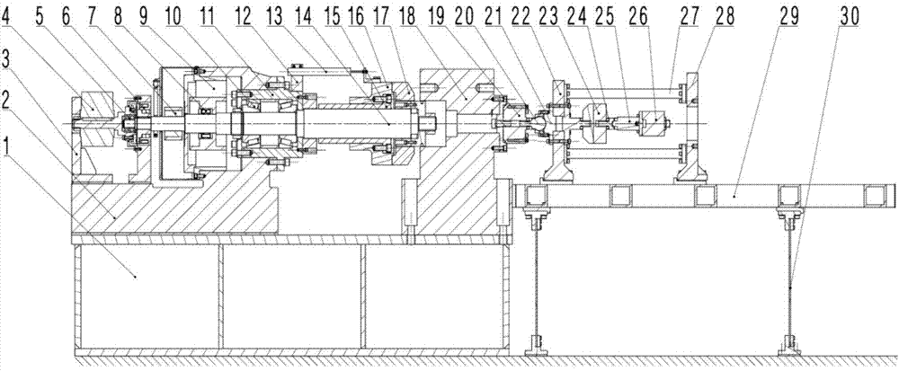
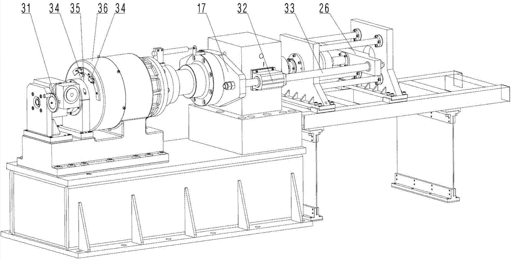
[0017] The present invention will be described in detail below in conjunction with the accompanying drawings.
[0018] As shown in the figure, the structure of the present invention mainly includes base 1, motor base 2, reducer bracket 3, double worm gear reducer 4, single row cylindrical roller bearing 5, electromagnetic clutch 6, encoder 7, tensioner sleeve 8 , DC torque motor 9, tapered roller bearing 10, bearing housing 11, displacement sensor mounting base 12, linear displacement sensor 13, ball screw 14, screw nut 15, screw nut seat 16, back beam 17, bearing frame 18, work Force sensor 19, working force sensor force transmission ball head 20, working force sensor force transmission ball socket 21, thrust frame back plate 22, standard force sensor 23, standard force sensor force transmission ball socket 24, standard force sensor force transmission ball head 25 , Force transmission frame front beam 26, thrust frame connecting rod 27, thrust frame front plate 28, moving fra...
PUM
Abstract
The invention belongs to the field of engine tests, discloses mechanical subsystems of in-situ calibrating systems, and relates to an in-situ calibrating device with a loaded direct-current torque motor and a loaded driving ball screw assembly. The in-situ calibrating device comprises the direct-current torque motor, the high-precision ball screw assembly, a high-precision encoder, a linear displacement sensor, a force transfer frame, a standard force sensor, a working force sensor, force transfer balls, force transfer ball sockets, a thrust frame, a force bearing frame, a motor base, a base, tapered roller bearings, a linear bearing, an electromagnetic clutch, double worm gear reducers, a hand wheel, an electric limit switch, a limit pressure plate and the like. The in-situ calibrating device has the advantages that an in-situ calibrating system comprises the in-situ calibrating device, a control subsystem of the in-situ calibrating system and a software subsystem of the in-situ calibrating system, an electric servo automatic control mechanical device loading method is implemented, accordingly, the in-situ calibrating device is high in in-situ calibrating loading force precision, is high in stability, good in safety and applicable to small-tonnage force and has an overload protection function, calibrating procedures can be automated, and manual loading modes are taken into consideration.
Description
technical field [0001] The invention belongs to the field of engine testing, is a mechanical sub-system of an in-situ calibration system, and relates to an in-situ calibration device for driving a ball screw pair loaded by a DC torque motor. Background technique [0002] Before the engine thrust test, it is an indispensable work to calibrate and check the working force sensor, which directly affects the reliability of the test process and the accuracy of the test data. At present, the static calibration and verification of the working force sensor on-line to simulate the actual working conditions, that is, the in-situ calibration method, has been adopted by the engine research and development departments and production units, which greatly improves the reliability of the data. In situ calibration loading is achieved by precisely controlling the displacement on the structure. At present, there is an in-situ calibration method that uses electro-hydraulic servo to control the ...
Claims
Application Information
Patent Timeline
Application Date:The date an application was filed.
Publication Date:The date a patent or application was officially published.
First Publication Date:The earliest publication date of a patent with the same application number.
Issue Date:Publication date of the patent grant document.
PCT Entry Date:The Entry date of PCT National Phase.
Estimated Expiry Date:The statutory expiry date of a patent right according to the Patent Law, and it is the longest term of protection that the patent right can achieve without the termination of the patent right due to other reasons(Term extension factor has been taken into account ).
Invalid Date:Actual expiry date is based on effective date or publication date of legal transaction data of invalid patent.